
Home page||Auxiliary Power ||
Turbo-generator construction- Ship service systems
Turbo-generator construction-For electrical power generation, turbines are conventionally horizontal axial flow machines of the impulse reaction type. They may exhaust either to an integral condenser (invariably underslung) or to a separate central auxiliary condenser or the ship's main condenser. A typical auxiliary condensing turbine is shown in Figure 7.14.
Alternatively the turbine may be a back-pressure unit in which the exhaust is used as a source of low pressure steam for other
services. The casings, split horizontally and supporting the rotors in plain journal bearings are cast mild steel or, for temperatures exceeding 460 deg C they are of 0.5% molybdenum steel, with cast or fabricated mild steel for parts not subject to high temperatures. Solid gashed rotors of chrome-molybdenum alloy steel are usual though some may be encountered having rotor spindles of this alloy, with shrunk and keyed bucket wheels.
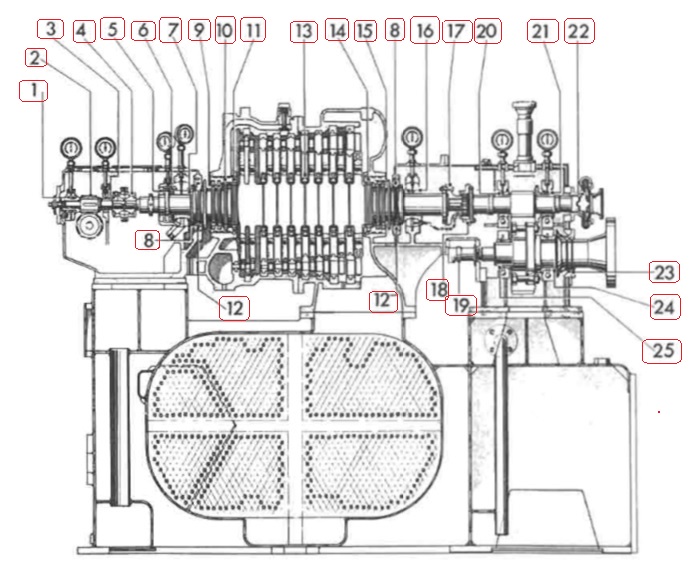
Figure 7.14 Auxiliary condensing turbine (Peter Brotherhood Ltd)
Figure 7.14 Auxiliary condensing turbine (Peter Brotherhood Ltd)details
Blades may be of stainless iron, stainless steel or monel metal, with shrouded tips, fitted into the rotors in a number of root forms. Depending on steam conditions and power the turbine will have a two row velocity compounded stage followed by a suitable number, probably five or more, single row pressure compounded stages, each separated by a cast steel nozzle.
Steam enters the turbine at the free end via a cast steel nozzle box and flows towards the drive end which is connected to the pinion of the reduction gearing by a fine tooth or other flexible coupling designed to accommodate longitudinal expansion of the rotor. Typical rotating speed of the rotor is about 6S00rev/min.
The diaphragms separating each stage are split horizontally and fitted in grooves in the casing, to which they are securely fixed so as not to be disturbed when the top half casing is lifted. The diaphragms may be of steel or cast iron depending on the stage pressure. Interstage leakage, where the rotor shaft passes through the diaphragm, is minimized by labyrinth glands of a suitable non-ferrous alloy such as nickel-bronze.
Labyrinth packing may also be used for the turbine shaft/casing glands which are steam-packed. In some turbines contact seals utilizing spring-loaded carbon segments as the sealing media, are used instead of the labyrinth gland (Figure 7.15).
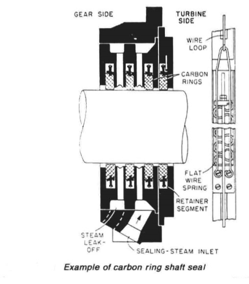
Figure 7,15 Example of carbon ring shaft seal
The low pressure labyrinth is divided into three separate groups so as to form two pockets. The inner pocket serves as an introduction annulus for the gland sealing steam; this flows inwards into the turbine and some escapes through the centre labyrinth into the outer pocket. The supply of sealing steam is regulated to keep the pressure in the outer pocket just above atmospheric. Surplus steam in the outer pocket is usually led to a gland steam condenser.
The gland at the high pressure end of the turbine is subject to a considerable pressure range from sub-atmospheric at low load to considerably above atmospheric at full load and is therefore arranged with three pockets. Gland steam is supplied to the centre pocket. The innermost pocket is
connected to a lower pressure stage further down the turbine, enabling the leakage steam to rejoin the main stream and do further work while the outermost pocket, connected to the gland condenser, prevents excessive leakage to atmosphere.
The labyrinth packings at both ends of the turbine and in the diaphragms are retained by T-heads on the outer peripheries which slot into matching grooves. Each gland segment is held in position by a leaf spring. The retaining lips of the T-head prevent inward movement and the arrangement permits temporary outward displacement of the segments. Rotating of the segments is prevented by stop plates or pegs fitted at the horizontal joint.
Although there is little residual end thrust on the rotor it is necessary to arrange a thrust bearing on the rotor shaft and it is normal to make this integral with the high-pressure end journal bearing. Sometimes the thrust is of multi-collar design but is more frequently a Michell-type tilting pad bearing.
Summarized below some of the basic procedure of marine auxiliary machinery :
- Auxiliary engine general construction
Major problems have been experienced on large slow-speed
engines with some of the poor quality bunkers such as those containing
catalytic fines. Fuel should conform to the specification given in the instruction
book for the engine.
......
- Auxiliary engine back pressure turbine
Many ships have used an auxiliary steam turbine as a primary pressure reducing stage before passing the steam to other auxiliaries demanding steam at a substantially lower pressure than that available. Such an arrangement gives a heat balance which is far more favourable than that obtained with a pressure reducing valve......
- Auxiliary engine fuel pump
The most common fuel pump used on auxiliary diesel engines is the Bosch
type. This is a cam operated jerk pump with a helical groove on the plunger to
control the fuel cut-off and therefore the quantity of fuel delivered to the
cylinder for combustion.
......
- Auxiliary engine common fuel injector
Fuel is delivered to an annular space in the nozzle via a hole, drilled through
the nozzle body from the inlet. The nozzle valve is forced from its seat in the
nozzle body by the pressure of fuel from the pump, acting on the shoulder of
the needle valve.
......
- Auxiliary engine cooling system
A variety of cooling systems may be adopted for marine auxiliary engines but
the most commonly used is the simple closed circuit system . Sea
water is passed through the intercooler, the oil cooler and then the jacket water
cooler in series flow.
......
- Auxiliary engine hydraulic governor
When used for alternating current power generation, a diesel engine is normally fitted with a hydraulic governor. This incorporates a centrifugal speed sensing device (spring loaded flyweights) controlling a suitably damped oil operated servo-cylinder through a pilot valve.
......
- Auxiliary engine speed governing system
Unlike propulsion turbines, generator turbines work at constant speed and must be governed accordingly. Classification Society rules require that there must be only a 10% momentary and a 6% permanent variation in speed when full load is suddenly taken off or put on.
......
- Auxiliary engine tracing faults
The failure of an engine to start or problems while running may be traced to
faults with the fuel injection system or other possible causes. Instruction
manual guidance on fault finding and remedies will include some of the typical
problems
......
- Generators driven from the main propulsion
Generators can variously be driven from the propeller shaft, through a gearbox or by being mounted on the engine itself.
......
- Exhaust gas boilers
The original exhaust gas boilers or economizers were of simple construction and produced, from the low powered engines of the time, a very moderate amount of steam. As large slow speed engine powers increased, the larger quantity of steam that could be generated from otherwise wasted exhaust energy,
......
- Auxiliary engine Turbo generator construction
Turbo-generator construction-For electrical power generation, turbines are conventionally horizontal axial flow machines of the impulse reaction type. They may exhaust either to an integral condenser (invariably underslung) or to a separate central auxiliary condenser or the ship's main condenser.
......
- Caterpillar engine fuel system
The range of larger Caterpillar engines use helix-type fuel pumps driven from a
separate camshaft.......
Home page||Cooling ||Machinery||Services ||Valves ||Pumps ||Auxiliary Power ||Propeller shaft ||Steering gears ||Ship stabilizers||Refrigeration||Air conditioning ||Deck machinery||Fire protection||Ship design
||Home ||
General Cargo Ship.com provide information on cargo ships various machinery systems -handling procedures, on board safety measures and some basic knowledge of cargo ships that might be useful for people working on board and those who working in the terminal. For any remarks please
Contact us
Copyright © 2010-2016 General Cargo Ship.com All rights reserved.
Terms and conditions of use
Read our privacy policy|| Home page||