
Home page||Marine Pumps ||
Centrifugal pumps working principles and charactestics
Rotation of a centrifugal pump impeller (Figure 1) causes the liquid it contains to move outwards from the centre to beyond the circumference of the impeller. The revolving liquid is impelled by centrifugal effect. It can only be projected into the casing around the periphery of the impeller if other liquid in the casing can be displaced. Displaced liquid in moving from the casing to the delivery pipe, causes flow in the discharge side of the system. The liquid in the impeller and casing of a centrifugal pump is also essential to its operation.
In moving out under the influence of the centrifugal effect, it drops the pressure at the centre, to which the suction or supply pipe delivers the liquid to be pumped. The moving liquid acts in the same way as a reciprocating pump piston on its suction stroke. Provided that a centrifugal pump is filled initially with liquid and that flow is maintained, the suction stroke action will continue. If such a purnp contains no liquid initially, it is as though an essential part is missing.
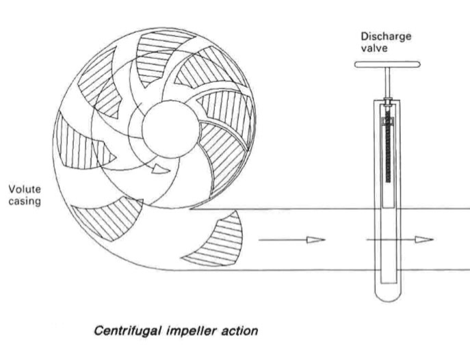
Figure 1: Centrifugal impeller action
The volute pump (Figures 2) is so called because of the shape of the casing. The object of the volute is gradually to reduce the velocity of the water after it leaves the impeller, and so convert part of its kinetic energy to pressure energy. For general purposes the volute pump is commonly used.
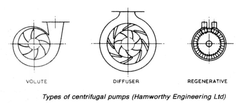
Figure 2: Types of centrifugal pumps (Hamworthy Engineering Ltd)
The diffuser pump (Figure 2) is so called because of the ring of guide passages around the impeller. The design is used for high pressure as in multi-stage boiler feed pumps. The diffuser passages are able to convert a larger amount of the kinetic energy of the liquid as it leaves the impeller into pressure energy.
A single stage diffuser pump is able to deliver to a much greater head than an ordinary
volute pump. The term turbine pump is sometimes used to describe the diffuser pump. Multi-stage deepwell pumps for bulk liquid cargoes may be referred to as turbine pumps. The regenerative pump (Figure 2) is used where a relatively high pressure and small capacity are required.
Centrifugal pump discharge characteristics
From a mathematical consideration of the action of a centrifugal pump it can be shown that the theoretical relationship between head, H, and throughput, Q, is a straight line (Figure 3), with minimum throughput occurring when the head is maximum. Because of shock and eddy losses caused by impeller blade
thickness and other mechanical considerations there will be some head loss, increasing slightly with throughput.
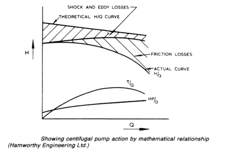
Figure 3: Showing centifugal pump action by mathematical relationship {Hamworthy Engineering Ltd.)
These losses, together with friction losses due to fluid contact with the pump casing and inlet and impact losses, result in the actual H/Q curve shown in the figure. The shape of this curve, shows the discharge characteristic which varies according to the design and features of the particular pump.
The discharge characteristic is obtained for a pump type, by measuring throughput (Q) through increase of head (H) during a test at constant speed. The actual discharge characteristic provides important information for the designer of a pumping system; it also explains why the throughput of a centrifugal pump alters with discharge head or back pressure.
A slow rate of discharge by a centrifugal cargo pump can be explained by increasing head due to a restricted or very long discharge pipe, high viscosity of the liquid, discharge to a storage tank sited at a high level or even a partly open valve on the discharge line.
Depending on application, centrifugal pumps can be designed with relatively flat H/Q curves or if required the curve can be steep to give a relatively large shut-off head.
From Figure 3 and from HP/Q, the power curve, that minimum power is consumed by the pump when there is no flow and when the discharge head is at its highest. This equates to the discharge valve being closed. Because maximum pressure with the discharge closed is only moderately above working pressure, a relief valve is not necessary for a centrifugal pump. It will be noticed that the efficiency curve for the pump is convex which means that maximum efficiency occurs at a point somewhere between maximum and minimum discharge head and throughput conditions.
In the case of a variable speed pump:
1 Head varies as the square of the speed. 2 Capacity varies directly as the speed. 3 Power varies as the cube of the speed since it is a function of head and capacity.
In the case of a constant speed pump:
1 Head varies as the square of the diameter. 2 Capacity varies as the diameter. 3 Power varies as the cube of the diameter.
Where the head in a given installation is known, the following formula could be used to calculate the necessary speed of the pump: N-95 2£ N~ ~D
where:
N=rev/min, D = diameter of impeller over blade tips in m, H total head in m, C = constant.
Pumps and pumping 149
The value of C varies considerably with pump shape but is generally between 1,05 and 1.2; the higher value being taken for pumps working considerably beyond their normal duty, or for pumps with impellers having small tip angles,
Centrifugal pumps - care
A centrifugal feed pump must not be operated unless it is fully primed. The pump casing should be filled before starting, the suction pipe and pipe branch
to the discharge stop valve must also be full. If the liquid enters the pump suction by gravity, priming is usually unnecessary and the pump will remain full of liquid when shut down. To prime a pump initially, or one that has become filled with air, open the small air cock on the top of the pump casing to release the air and close it when liquid commences to flow.
If the pump is operating with a suction lift, it may be primed either from an independent supply, for example by opening the sea suction of a ballast pump, or by means of an exhauster or priming system, which will evacuate air from the pump and suction piping. The discharge valve is kept closed while priming the pump.
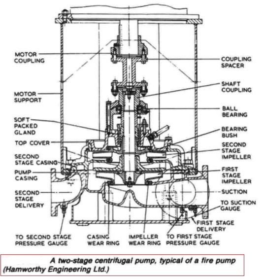
Figure : Two stage centrifugal pump
Summarized below some of the basic procedure of marine pumps and pumping system onboard :
- Axial flow pumps
An axial flow pump is one in which a screw propeller is used to create an increase in pressure by causing an axial acceleration of liquid within its blades. The incidental rotation imparted to the liquid is converted into straight axial movement by suitably shaped outlet guide vanes.....
- centrifugal pumps
Rotation of a centrifugal pump impeller causes the liquid it contains to move outwards from the centre to beyond the circumference of the impeller. The revolving liquid is impelled by centrifugal effect.....
- Centrifugal pump cavitation
Because of their self-priming ability, positive displacement pumps are widely used for lubricating oil duties. This practice is completely satisfactory in installations where the pump speed is variable but when the pump is driven by a constant speed a.c. motor it is necessary to arrange a bypass which can be closed in to boost flow. ....
- Gear pumps
Diesel engine and gearbox lubrication systems are normally supplied by gear
pumps which are independently driven for large slow speed engines and
stand-by duties but usually shaft driven for medium and high speed engines.
Gear pumps are also used for fuel and oil transfer, boiler combustion systems
and other duties.....
- General pumping system characteristics
A pump divides its pipe system into two distinct parts, each with different
characteristics. These are the suction and discharge sides. On the suction side
the drop in pressure that can be produced by a pump is limited to that of an
almost perfect vacuum. On the discharge side there is theoretically, no limit to
the height through which a liquid can be raised.....
- General purpose pumps
Single entry general purpose pumps are used for salt and fresh water circulating and also for bilge and ballast duties. The impeller is suspended from the shaft with no bottom support. ....
- Lobe pumps
Lobe pumps as manufactured by Stothert and Pitt have inner and outer
elements which rotate in a renewable liner fitted in the pump body. The inner
rotor is eccentric to the outer and is fitted to a shaft located by bearings in the
pump covers....
- Marine pumps construction
Marine pumps are usually installed with the shaft vertical and the motor above the pump. This positions the pump as low as possible for the best NPSH, takes up the least horizontal space and leaves the electric motor safer from gland or other leakage.....
- Pumps erosion
A pump handling liquids which contain abrasives, will suffer erosion on all internal surfaces, including bearings and shaft seals. The sea-water circulating pumps of ships operating in waters that contain large quantities of silt and sand
require frequent renewal of shaft seals or packing, also of shaft sleeves in way of the gland and bearings.....
- Rotary displacement pump
Positive displacement rotary pumps rely on fine clearances between moving
parts for their efficient operation. Excessive wear or erosion of parts, due to
friction contact or the presence of abrasives, is avoided by employing this type
of pump for specialized rather than general duties......
- Screw pumps
Both double-screw pumps, in which the screws are driven in phase by timing
gears , and triple screw pumps , in which the centre
screw is driven and the outer screws idle are used at sea especially for pumping
high viscosity liquids such as oil and some liquid cargoes.....
Home page||Cooling ||Machinery||Services ||Valves ||Pumps ||Auxiliary Power ||Propeller shaft ||Steering gears ||Ship stabilizers||Refrigeration||Air conditioning ||Deck machinery||Fire protection||Ship design
||Home ||
General Cargo Ship.com provide information on cargo ships various machinery systems -handling procedures, on board safety measures and some basic knowledge of cargo ships that might be useful for people working on board and those who working in the terminal. For any remarks please
Contact us
Copyright © 2010-2016 General Cargo Ship.com All rights reserved.
Terms and conditions of use
Read our privacy policy|| Home page||