
Home page||General service system ||
Salinometer working principles & procedure for ship service systems
The condensate or product, if of acceptable quality, is delivered to the appropriate tanks by the distilled water pump. Quality is continuously tested by the salinometer both at start up and during operation. If the device registers an excess of salinity it will dump the product and activate the alarm using its solenoid valves. The product is recirculated in some installations.
The electric salinometer
Pure distilled water may be considered a non-conductor of electricity. The addition of impurities such as salts in solution increases the conductivity of the water, and this can be measured. Since the conductivity of the water is, for low concentrations, related to the impurity content, a conductivity meter can be used to monitor the salinity of the water. The instrument can be calibrated in units of conductivity (micromhos) or directly in salinity units (older instruments in grains/gall, newer instruments in pprn or mg/litre) and it is on
this basis that electric salinometers (Figure 1) operate.
The probe type electrode cell (Figure 2) is fitted into the pipeline from the evaporator, co-axially through a retractable valve which permits it to be withdrawn for examination and cleaning. The cell cannot be removed while the valve is open and consists of two stainless steel concentric electrodes having a temperature compensator located within the hollow inner electrode.
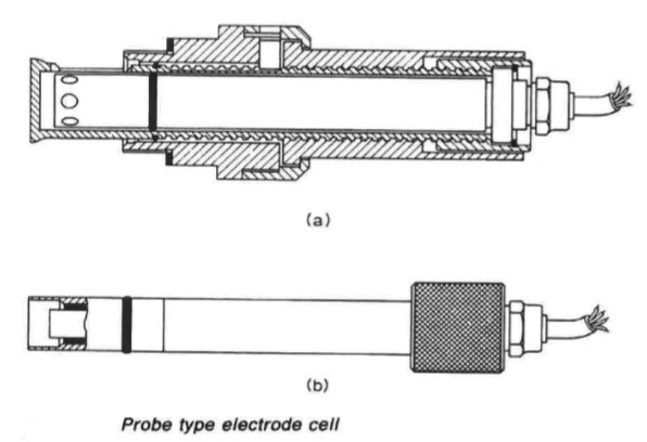
Figure 2: Probe type electrode cell
It operates within the limits of water pressure up to 10.5 bar and water temperatures between 15 and 110 deg C. The incoming a.c. mains from control switch S2 through fuses FS, feed transformer T. A pilot lamp SLl on the 24 V secondary winding indicates the circuit is live. The indicating circuit comprises an applied voltage across the electrode cell and the indicator. The indicator shows the salinity by measuring the current which at a preset value actuates the alarm circuit warning relay.
The transformer cell tapped voltage is applied across a series circuit comprising the bridge rectifier Mrec, the current limiting resistor Rl and the electrode cell. The current from rectifier Mrec divides into two paths, one through the temperature compensator F via resistor R2 and the other through the alarm relay potentiometer (Pot) indicator MA and resistor R3, the two paths joining in a common return to the low potential side of the rectifier. The indicator is protected from overload by a semi-conductor in shunt across the indicator and potentiometer. When the water temperature is at the lower limit of the compensated range the total resistance of the compensator is in circuit and the two paths are as described above.
As the temperature of the water rises, the resistance of the compensator device drops progressively, the electrical path through the compensator now has a lower resistance than the other and a large proportion of the cell current. The compensator therefore ensures that the alteration in the balance of the resistances of the two paths corresponds to the increased water conductivity due to the rise in temperature and a correct reading is thus obtained over the compensated range. The alarm setting is adjustable and the contacts of the warning relay close to light a lamp or sound a horn when salinity exceeds the acceptable level.
The salinometer is also arranged to control a solenoid operated valve which dumps unacceptable feed water to the bilge or recirculates. The salinometer and valve reset automatically when the alarm condition clears.
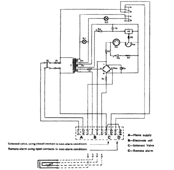
Figure 1: Schematic diagram of saline-meter (W. Crockatt & Sons Ltd)
Summarized below some of the basic procedure of machinery service systems and equipment :
- Ballast arrangements
The ballasting of a vessel which is to proceed without cargo to the loading port is necessary for a safe voyage, sometimes in heavy weather conditions. On arrival at the port the large amount of ballast must be discharged rapidly in readiness for loading....
- Cargo ships bilge systems
The essential purpose of a bilge system, is to clear water from the ship's 'dry' compartments, in emergency. The major uses of the system, are for clearing water and oil which accumulates in machinery space bilges as the result of leakage or draining, and when washing down dry cargo holds. The bilge main in the engine room, has connections from dry cargo holds, tunnel and machinery spaces.....
- Bilge system layout details
All bilge suctions have screw down non-return valves with strainers or mud boxes at the bilge wells. Oily bilges and purifier sludge tanks have suitable connections for discharge to the oily water separator or ashore. The system is tailored to suit the particular ship......
- Domestic water system
Systems using gravity tanks to provide a head for domestic fresh and sanitary water, have long been superseded by schemes where supply pressure is maintained by a cushion of compressed air in the service tanks....
- Reverse osmosis
Osmosis is the term used to describe the natural migration of water from one side of a semi-permeable membrane into a solution on the other side. The
phenomenon occurs when moisture from the soil passes through the membrane covering of the roots of plants,....
- Salinometer features
The condensate or product, if of acceptable quality, is delivered to the appropriate tanks by the distilled water pump. Quality is continuously tested by the salinometer both at start up and during operation. If the device registers an excess of salinity it will dump the product and activate the alarm using its solenoid valves. The product is recirculated in some installations......
- Sewage systems
The exact amount of sewage and waste water flow generated on board ship is difficult to quantify. European designers tend to work on the basis of 70 litres/person/day of toilet waste (including flushing water) and about 130-150 litres/person/day of washing water (including baths, laundries, etc.). US authorities suggest that the flow from toilet discharges is as high as 114 litres/person/day with twice this amount of washing water......
- Sewage zero discharge system
A retention or holding tank is required where no discharge of treated or untreated sewage is allowed in a port area. The sewage is pumped out to shore reception facilities or overboard when the vessel is proceeding on passage at sea, usually beyond the 12 nautical mile limit. ...
- Biological sewage treatment
A number of biological sewage treatment plant types are in use at sea but nearly all work on what is called the extended aeration process. Basically this consists of oxygenating by bubbling air through or by agitating the surface. ....
- Sterilization system
Sterilization by the addition of chlorine, is recommended in Merchant Shipping Notice M1214. A later notice, M1401, states that the Electro-Katadyn process in use since the 1960s, has also been approved. Another problem with distilled water is that having none of the dissolved solids common in fresh water it tastes flat. It also tends to be slightly acidic due to its ready absorption of carbon dioxide (CO2). .....
- Treatment of water from shore
There is a risk that water supplied from ashore may contain harmful organisms which can multiply and infect drinking or washing water storage tanks. All water from ashore, whether for drinking or washing purposes, is to be sterilized. When chlorine is used, the dose must be such as to give a concentration of 0.2 ppm....
- Water production low pressure evaporator
A considerable amount of fresh water is consumed in a ship. The crew uses on average about 70 litre/person/day and in a passenger ship, consumption can be as high as 225 litre/person/day. Water used in the machinery spaces as make up for cooling system losses may be fresh or distilled but distilled water is essential for steam plant where there is a water tube boiler.
Steamship consumption for the propulsion plant and hotel services can be as high as 50 tonnes/day.....
- Flash evaporator system
The evaporator , boils sea water at the saturation temperature corresponding to the uniform pressure through the evaporation and condensing chambers. With flash evaporators the water is heated in one compartment before being released into a second chamber in which the pressure is substantially lower......
- Oil content monitor system
In the past, an inspection glass, fitted in the overboard discharge pipe of the oil/water separator permitted sighting of the flow. The discharge was illuminated by a light bulb fitted on the outside of the glass port opposite the viewer......
- Oily water separator
Oil/water separators are necessary aboard vessels to prevent the discharge of oil overboard mainly when pumping out bilges. They also find service when deballasting or when cleaning oil tanks. The requirement to fit such devices is the result of international legislation....
Home page||Cooling ||Machinery||Services ||Valves ||Pumps ||Auxiliary Power ||Propeller shaft ||Steering gears ||Ship stabilizers||Refrigeration||Air conditioning ||Deck machinery||Fire protection||Ship design
||Home ||
General Cargo Ship.com provide information on cargo ships various machinery systems -handling procedures, on board safety measures and some basic knowledge of cargo ships that might be useful for people working on board and those who working in the terminal. For any remarks please
Contact us
Copyright © 2010-2016 General Cargo Ship.com All rights reserved.
Terms and conditions of use
Read our privacy policy|| Home page||