
Home page||Ship stabilizers||
Tank stabilizers- Generating anti-rolling forces & Ship propulsiom systems
Tank stabilizers (like bilge keels) are virtually independent of the forward speed
of the vessel. They generate anti-rolling forces by phased flow of appropriate
masses of fluid, usually water, in tanks installed at suitable heights and distances
from the ship's centre line.
Fluid transfer may be by open flume or from and to
wing tanks connected by cross ducts. The tank/fluid combination constitutes a
damped mass elastic system having its own natural period and capable of
developing large forces at resonance with the impressed wave motion.
Since the fluid can only flow downhill and has inertia, it cannot start to move
until the ship has rolled a few degrees (Figure 10.15). The natural restoring
forces limit the maximum roll angle and initiate roll in the opposite sense. In the
meantime the fluid continuing to flow downhill, piles up on the still low side
and provides a moment opposing the ship motion. As the ship returns and
passes its upright position, fluid again flows downhill to repeat the process.
The fluid flow tends to lag a quarter of a cycle behind the ship motion, a
phase lag of approximately 90 deg , to generate a continuing stabilizing moment.
This is due, mainly, to the transfer of the centre of gravity of the fluid mass
away from the centre line of the ship. The transverse acceleration of the fluid
generates an inertia force and thereby a moment, about the roll centre, which
reduces the gravity moment when the tanks are below the roll centre and
increases it when they are above.
In practice, tanks may be placed 20% off the
beam below the roll centre without serious loss of performance. Above the roll
centre, other factors associated with the phase of fluid motion prevent
augmentation of the gravity stabilizing power being realized. The phase lag
may be increased, within limits, by placing orifice plates or grillages in the fluid
flow path, to increase the damping.
In the wing tank system the mode of operation is similar to the simple flume
but the tank geometry combined with the dynamic amplification of the flow
tends to make fluid pile up to a greater height at a greater distance from the
ship's centre line to give more effective stabilization. The wing tanks must be of
sufficient depth to accommodate the maximum rise of the fluid without
completely filling them.
The natural period of the fluid is a function of
tank geometry and the volume of fluid contained. It is arranged to be equal to
or slightly less than the lowest natural roll frequency of the ship. Provided the
system has little damping, maximum roll reduction is achieved at resonance
and the roll amplitude/roll period characteristic is virtually a straight line at
about the optimum residual roll characteristic.
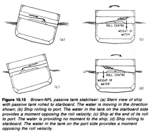
Figure : Brown-NPL passive tank stabiliser
Figure 10.15 Brown-NPL passive tank stabiliser: (a) Stem view of ship
with passive tank rolled to starboard. The water is moving in the direction
shown; (b) Ship rolling to port. The water in the tank on the starboard side
provides a moment opposing the roll velocity; (c) Ship at the end of its roll
to port. The water is providing no moment to the ship; (d) Ship rolling to
starboard. The water in the tank on the port side provides a moment
opposing the roll velocity.
Anti-heeling tanks
Container ships and RO-RO (roll onroll off) vessels are usually fitted with
anti-heel tanks which enable the ship to be kept upright during uneven loading
of cargo. Transfer of liquid from one tank to the other is by pump or
compressed air.
Controlled passive system stabilizing tanks are used in the anti-heeling
arrangements of some ships. The simplest method in this scheme, for
transferring the liquid, makes use of compressed air admitted to the top of
either tank, to force the liquid from one to the other.
Summarized below ship stabilizing system detail guideline:
- Ships bow thrusters-Electric drives, diesel drives, hydraulic drives & white Gill type
Safety is increased when berthing in adverse
weather conditions provided that the required thruster capacity has been
correctly estimated. Transverse thrusters are installed to facilitate the
positioning of some types of workboats.
More .....
- Fin stabilizers and stabilizing systems
The stabilizing power of fins is generated by their movement through the sea and lift' created by the flow of water above and below the 'aerofoil' or hydrofoil shape. When the front edge of the fin is tilted up, water flow across the top of the profile produces lift due to a drop in pressure while a lifting pressure is provided by flow along the underside.More.....
- Folding fin stabilizer & Retractable fin stabilizers-
Housing and extending the fin is achieved by a double acting hydraulic
cylinder connected to the upper part of the trunnion. Power units, control and
sensing equipment are generally similar to other types of stabilizer except that
feed-back of fin angle is accomplished electrically by synchros.More....
- Tank stabilizers
Tank stabilizers (like bilge keels) are virtually independent of the forward speed
of the vessel. They generate anti-rolling forces by phased flow of appropriate
masses of fluid, usually water, in tanks installed at suitable heights and distances
from the ship's centre line.More....
Home page||Cooling ||Machinery||Services ||Valves ||Pumps ||Auxiliary Power ||Propeller shaft ||Steering gears ||Ship stabilizers||Refrigeration||Air conditioning ||Deck machinery||Fire protection||Ship design
||Home ||
General Cargo Ship.com provide information on cargo ships various machinery systems -handling procedures, on board safety measures and some basic knowledge of cargo ships that might be useful for people working on board and those who working in the terminal. For any remarks please
Contact us
Copyright © 2010-2016 General Cargo Ship.com All rights reserved.
Terms and conditions of use
Read our privacy policy|| Home page||