
Home page||Cooling ||
Steam-jet air ejector for motor ships
Steam-jet air ejector
A steam-jet ejector may be used to withdraw air and dissolved gases from the condenser. In each stage of the steam-jet ejector, high pressure steam is expanded in a convergent/divergent nozzle. The steam leaves the nozzle at a very high velocity in the order of 1220 m/s and a proportion of the kinetic energy in the steam jet transferred, by interchange of momentum, to the body of air which is entrained and passes along with the operating steam through a diffuser in which the kinetic energy of the combined stream is re-converted to pressure energy.
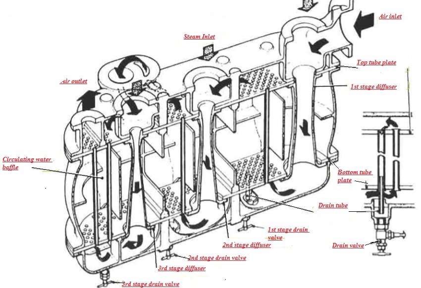
The maximum pressure ratio that can be obtained with a single stage is roughly 5:1 and consequently it is necessary to use two or even three stages in series, to establish a vacuum in the order of 724 mm Hg, with reasonable steam consumption. There are a variety of ejector designs in service which work on the same principle. Older units have heavy cast steel shells which serve as vapour condensers and also contain the difrusers. These are arranged vertically, the steam entering at the top (Figure 1).
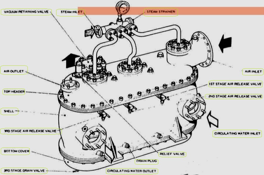
Figure 1: Three stage air ejector with internal diffusers
More recent designs have the difrusers arranged externally and the vapour condenser shell is somewhat lighter in construction. Horizontal and vertical arrangements can be found and some units are arranged as combined air ejectors and gland steam condensers.
Horizontal single element two stage air ejector
An air ejector which has been commonly used, is shown schematically in Figure 2. The unit comprises a stack of U-tubes contained in a fabricated mild steel condenser shell on which is mounted a single element two stage air ejector.
The condensate from the main or auxiliary condenser is used as the cooling medium, the condensate circulating through the tubes whilst the air and vapour passes through the shell. The high velocity operating steam emerging from the first stage ejector nozzle entrains the non-condensables and vapour from the main condenser and the mixture discharges into the inter (or first stage) condenser.
Most of the steam and vapour is condensed when it comes into contact with the cool surface of the tubes, falls to the bottom of the shell and drains to the main or auxiliary condenser. The remaining air and water vapour are drawn into the second stage ejector and discharged to the after (or second stage) condenser. The condensate then passes to the steam drains tank and the non-condensables are discharged to the atmosphere through a vacuum retaining valve.
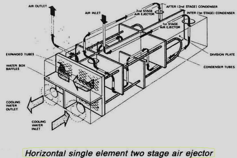
Figure 2: Horizontal single element two stage air ejector
The vacuum retaining valve is shown in Figure 3 which is fitted as a safety device to reduce the rate of loss of vacuum in the main condenser if the air ejector fails. It is mounted on a pocket built out from the second stage condenser, and consists essentially of a light stainless steel annular valve plate which covers ports in a gunmetal valve seat. When the pressure inside the after condenser exceeds atmospheric pressure the valve lifts and allows the gases to escape to atmosphere.
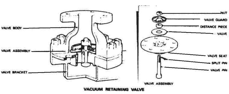
Figure 3: vacuum retaining valve
A relief valve is fitted on the first stage condenser shell of the twin element unit. The ejector stages, Figure 4, consist of monel metal nozzles in mild steel holders discharging into gunmetal difrusers. Expansion is allowed for by sliding feet at the inlet end.
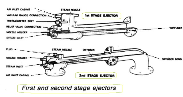
Figure 4: First and second stage air ejectors
Summarized below various circulating systems for motorships, some of the basic procedure of heat exchangers & control of temperatures:
- Sea water circulation-systems
The usual arrangement for motorships has been to have sea-water circulation of coolers for lubricating oil, piston cooling, jacket water, charge air, turbo-charger oil (if there are sleeve type bearings) and fuel valve cooling, plus direct sea-water cooling for air compressors and evaporators....
-
Shell and tube heat exchangers for engine cooling water and lubricating oil cooling
Shell and tube heat exchangers for engine cooling water and lubricating oil cooling have traditionally been circulated with sea water. The sea water is in contact with the inside of the tubes, tube plates and water boxes....
-
Plate type heat exchanger
The obvious feature of plate type heat exchangers, is that they are easily opened for cleaning. The major advantage over tube type coolers, is that their higher efficiency is reflected in a smaller size for the same cooling capacity....
-
Details of charged air cooler
The charge air coolers fitted to reduce the temperature of air after the turbo-charger and before entry to the diesel engine cylinder, are provided with fins on the heat transfer surfaces to compensate for the relatively poor heat transfer properties of air....
-
Maintenance of heat exchangers
The only attention that marine heat exchangers should require is to ensure that the heat transfer surfaces should remain substantially clean and flow passage generally clear of obstructions. Indcation that fouling has occured is given by a progressive increase in the temperature difference between the two fluids, and change of pressure....
-
Central cooling system & Scoop arrangement for motorships
The corrosion and other problems associated with salt water circulation systems can be minimized by using it for cooling central coolers through which fresh water from a closed general cooling circuit is passed. The salt water passes through only one set of pumps, valves and filters and a short length of piping.....
-
Circulating systems for steamships
The main sea-water circulating system for a ship with main propulsion by steam turbine is similar to that of a motorship with a central cooling system. The difference is that the sea water passes through a ....
- Closed feed system and feed heating for motor ships
To ensure trouble-free operation of water-tube boilers the feed water must be of high quality with a minimal solid content and an absence of dissolved gases. Solids are deposited on the inside surfaces of steam generating tubes,....
- Marine condenser assembly
A condenser is a vessel in which a vapour is deprived of its latent heat of vaporization and so is changed to its liquid state, usually by cooling at constant pressure. In surface condensers, steam enters at an upper level, passes over tubes in which cold sea water circulates, falls as water to the bottom and is removed by a pump (or flows to a feed tank)....
-
Three stage air ejector with internal diffusers
A steam-jet ejector may be used to withdraw air and dissolved gases from the condenser. In each stage of the steam-jet ejector, high pressure steam is expanded in a convergent/divergent nozzle. ...
- Pressure governor for motor ships
The main feature of the governor is that if the pump loses suction the steam ports are opened wide, allowing the pump to accelerate rapidly to the speed at which the emergency trip acts....
- Liquid ring pump- Nash rotary liquid ring pumps
Nash rotary liquid ring pumps, in association with atmospheric air ejectors, may be used instead of diffuser-type steam ejectors and are arranged as shown...
- The Weir electro-feeder - a multi-stage centrifugal pump
A multi-stage centrifugal pump mounted on a common baseplate with its electric motor. The number of stages may vary from two to fourteen depending upon the capacity of the pump and the required discharge pressure....
- Feed water heaters for motor ships
Surface or direct contact feed heaters, play an important part in the recovery of latent heat from exhaust steam. Direct contact feed heaters are also known as de-aerators....
- Devaporizer & turbo-feed pump
If the de-aerator cannot be vented to atmosphere or to a gland condenser satisfactorily, a devaporizer is connected to the vapour outlet condensing the vapour vented with the non-condensable gases and cooling these gases before they are discharged. ...
- Typical de-aerator & Cascade trays
Normally, the de-aerator is mounted directly on a storage tank, into which the de-aerated water falls, to be withdrawn through a bottom connection by a pump or by gravity. The tank usually has a capacity....
Home page||Cooling ||Machinery||Services ||Valves ||Pumps ||Auxiliary Power ||Propeller shaft ||Steering gears ||Ship stabilizers||Refrigeration||Air conditioning ||Deck machinery||Fire protection||Ship design
||
General Cargo Ship.com provide information on cargo ships various machinery systems -handling procedures, on board safety measures and some basic knowledge of cargo ships that might be useful for people working on board and those who ashore. For any remarks please
Contact us
Copyright © 2010-2016 General Cargo Ship.com All rights reserved.
Terms and conditions of use
Read our privacy policy|| Home page||