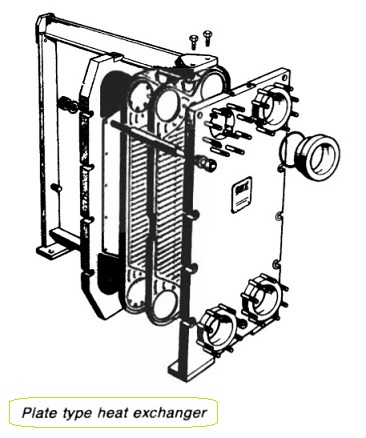
Figure 1: Plate type heat exchanger
Plate heat exchangers are cleaned by unclamping the stack of plates and exposing the surfaces. Plate surfaces are carefully washed using a brush or dealt with as recommended by the manufacturer to avoid damage. If the plate seals require replacement they may be removed with the method described in the section on plate coolers.
Prising seals from their bonding, e.g. with sharp tools, causes plate damage. Corrosion by sea water may occasionally cause perforation of heat transfer surfaces with resultant leakage of one fluid into the other. Normally the sea water is maintained at a lower pressure than the jacket water and other liquids that it cools, to reduce the risk of sea water entry to engine spaces. Leakage is not always detected initially if header or drain tanks are automatically topped up or manual top up is not reported.
Substantial leaks become evident through rapid loss of lubricating oil or jacket water and operation of low level alarms.
The location of a leak in a shell and tube cooler is a simple procedure. The heat exchanger is first isolated from its systems and after draining the sea water and removing the end covers or headers to expose the tube plates and tube ends, an inspection is made for evidence of liquid flow or seepage from around tube ends or from perforations in the tubes. The location of small leaks is aided if the surfaces are clean and dry.
The fixing arrangement for the tube stack should be checked before removing covers or headers to ensure that the liquid inside will not dislodge the stack. This precaution also underlines the need for isolation of a cooler from the systems. To aid the detection of leaks in a large cooler such as a main condenser, in which it is difficult to get the tubes dry enough to witness any seepage, it is usual to add a special fluorescent dye to the shell side of the cooler. When an ultra-violet light is shone on to the tubes and tube plates leaks are made visible because the dye glows.
Plate heat exchanger leaks can be found by visual inspection of the plate surfaces or they are cleaned and sprayed with a fluorescent dye penetrant on one side. The other side is then viewed with the aid of an ultra-violet light to show up any defects. Leaks in charge air coolers allow sea water to pass through to the engine cylinder. This can be a problem in four-stroke engines because there is a
tendency for salt scale to form on air inlet valve spindles and this makes them stick. The charge air manifold drain is regularly checked for salt water. Location of the leak may be achieved by having a very low air pressure on the air side and inspecting the flooded sea-water side for air bubbles. Soapy water could be used as an alternative to having the sea-water side flooded.
If a ship is to be out of service for a long period, it is advisable to drain the sea-water side of heat exchangers then clean and flush through with fresh water, after which the heat exchanger should be left drained, if possible until the ship re-enters service.
Venting and draining
It is important that any heat exchanger through which sea water flows should run full. In vertically-mounted single-pass heat exchangers of the shell-and-tube or plate types, venting will be automatic if the sea-water flow is upwards. This is also the case with heat exchangers mounted in the horizontal attitude, with single- or multi-pass tube arrangements, provided that the sea-water inlet branch faces downwards and the outlet branch upwards. With these arrangements, the water will drain virtually completely out of the heat exchanger when the remainder of the system is drained.
With other arrangements, a vent cock fitted at the highest point in the heat exchanger should be opened when first introducing sea water into the heat exchanger and thereafter periodically to ensure that any air is purged and that the sea-water side is full. A drain plug should be provided at the lowest point.
Heat exchange theory
The rate of flow of heat through a heat exchanger tube or plate from the fluid at the higher temperature to the one at the lower is related to the temperature difference between the two fluids, the ability of the material of the tube or plate to conduct and the area and thickness of the material.
If neither fluid is moving, the conductivity of the fluids has also to be taken into account and the fact that with static conditions as one fluid loses heat and the other gains, the temperature difference is reduced and this progressively slows down the rate of heat transfer. With slow moving liquids at either side of a jacket cooler heat exchange surface, there is likely to be a constant temperature difference provided the hotter fluid is receiving heat from a steady source (as from a cylinder water jacket) and there is a continuous source for the cooler fluid (circulation from the sea).
Laminar flow occurs in slow moving liquids with the highest velocity in the centre of the liquid path and a gradually slower rate towards containing surfaces. A static boundary layer tends to form on containing surfaces and heat flow through such a layer relies on the ability of the layer to conduct.
The faster moving layers also receives heat mainly by conductivity.
Summarized below various circulating systems for motorships, some of the basic procedure of heat exchangers & control of temperatures:
- Sea water circulation-systems
The usual arrangement for motorships has been to have sea-water circulation of coolers for lubricating oil, piston cooling, jacket water, charge air, turbo-charger oil (if there are sleeve type bearings) and fuel valve cooling, plus direct sea-water cooling for air compressors and evaporators....
-
Shell and tube heat exchangers for engine cooling water and lubricating oil cooling
Shell and tube heat exchangers for engine cooling water and lubricating oil cooling have traditionally been circulated with sea water. The sea water is in contact with the inside of the tubes, tube plates and water boxes....
-
Plate type heat exchanger
The obvious feature of plate type heat exchangers, is that they are easily opened for cleaning. The major advantage over tube type coolers, is that their higher efficiency is reflected in a smaller size for the same cooling capacity....
-
Details of charged air cooler
The charge air coolers fitted to reduce the temperature of air after the turbo-charger and before entry to the diesel engine cylinder, are provided with fins on the heat transfer surfaces to compensate for the relatively poor heat transfer properties of air....
-
Maintenance of heat exchangers
The only attention that marine heat exchangers should require is to ensure that the heat transfer surfaces should remain substantially clean and flow passage generally clear of obstructions. Indcation that fouling has occured is given by a progressive increase in the temperature difference between the two fluids, and change of pressure....
-
Central cooling system & Scoop arrangement for motorships
The corrosion and other problems associated with salt water circulation systems can be minimized by using it for cooling central coolers through which fresh water from a closed general cooling circuit is passed. The salt water passes through only one set of pumps, valves and filters and a short length of piping.....
-
Circulating systems for steamships
The main sea-water circulating system for a ship with main propulsion by steam turbine is similar to that of a motorship with a central cooling system. The difference is that the sea water passes through a ....
- Closed feed system and feed heating for motor ships
To ensure trouble-free operation of water-tube boilers the feed water must be of high quality with a minimal solid content and an absence of dissolved gases. Solids are deposited on the inside surfaces of steam generating tubes,....
- Marine condenser assembly
A condenser is a vessel in which a vapour is deprived of its latent heat of vaporization and so is changed to its liquid state, usually by cooling at constant pressure. In surface condensers, steam enters at an upper level, passes over tubes in which cold sea water circulates, falls as water to the bottom and is removed by a pump (or flows to a feed tank)....
-
Three stage air ejector with internal diffusers
A steam-jet ejector may be used to withdraw air and dissolved gases from the condenser. In each stage of the steam-jet ejector, high pressure steam is expanded in a convergent/divergent nozzle. ...
- Pressure governor for motor ships
The main feature of the governor is that if the pump loses suction the steam ports are opened wide, allowing the pump to accelerate rapidly to the speed at which the emergency trip acts....
- Liquid ring pump- Nash rotary liquid ring pumps
Nash rotary liquid ring pumps, in association with atmospheric air ejectors, may be used instead of diffuser-type steam ejectors and are arranged as shown...
- The Weir electro-feeder - a multi-stage centrifugal pump
A multi-stage centrifugal pump mounted on a common baseplate with its electric motor. The number of stages may vary from two to fourteen depending upon the capacity of the pump and the required discharge pressure....
- Feed water heaters for motor ships
Surface or direct contact feed heaters, play an important part in the recovery of latent heat from exhaust steam. Direct contact feed heaters are also known as de-aerators....
- Devaporizer & turbo-feed pump
If the de-aerator cannot be vented to atmosphere or to a gland condenser satisfactorily, a devaporizer is connected to the vapour outlet condensing the vapour vented with the non-condensable gases and cooling these gases before they are discharged. ...
- Typical de-aerator & Cascade trays
Normally, the de-aerator is mounted directly on a storage tank, into which the de-aerated water falls, to be withdrawn through a bottom connection by a pump or by gravity. The tank usually has a capacity....
Home page||
Cooling ||
Machinery||
Services ||
Valves ||
Pumps ||
Auxiliary Power ||
Propeller shaft ||
Steering gears ||
Ship stabilizers||
Refrigeration||
Air conditioning ||
Deck machinery||
Fire protection||
Ship design
||
Home ||
General Cargo Ship.com provide information on cargo ships various machinery systems -handling procedures, on board safety measures and some basic knowledge of cargo ships that might be useful for people working on board and those who working in the terminal. For any remarks please
Contact us
Copyright © 2010-2016 General Cargo Ship.com All rights reserved.
Terms and conditions of use
Read our privacy policy|| Home page||