
Home page||Refrigeration system||
Automatic direct expansion refrigeration
Vapour compression cycle:
The basic components of any refrigeration system (Figure 11.1) working on the
vapour compression cycle, are the compressor, condenser, expansion valve,
evaporator and the refrigerant fluid which is alternately vaporized and liquefied
during the refrigeration cycle. The temperature at which a fluid boils or
condenses, is known as the saturation temperature and varies with pressure.
The compressor in a refrigeration system in raising the pressure of the
vaporized refrigerant, causes its saturation temperature to rise, so that it is
higher than that of the sea water or air, cooling the condenser. The compressor
also promotes circulation of the refrigerant by pumping it around the system.
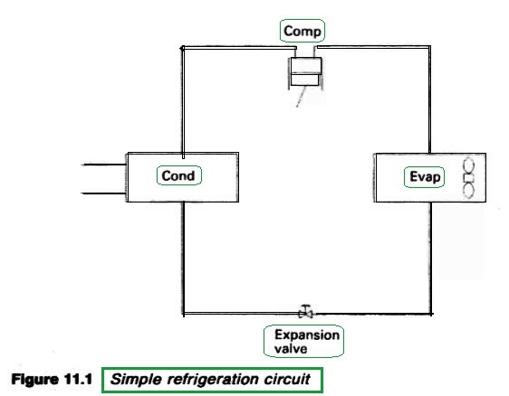
Figure : Simple refrigeration circuit
In the condenser, the refrigerant is liquefied by being subcooled to below the
saturation temperature relating to the compressor delivery pressure, by the
circulating sea water (or air for domestic refrigerators). Latent heat, originally
from the evaporator, is thus transferred to the cooling medium. The liquid
refrigerant, still at the pressure produced by the compressor, passes to the
receiver and then to the expansion valve.
The expansion valve is the regulator through which the refrigerant flows
from the high pressure side of the system to the low pressure side. Its throttling
effect dictates the compressor delivery pressure which must be sufficient to
give the refrigerant a saturation temperature which is higher than the
temperature of the cooling medium.
The pressure drop through the regulator causes the saturation temperature
of the refrigerant to fall, so that it will boil at the low temperature of the
evaporator. In fact, as the liquid passes through the expansion valve, the
pressure drop makes its saturation temperature fall below its actual temperature,
Some of the liquid boils off at the expansion valve, taking latent heat from the
remainder and causing its temperature to drop.
The expansion valve throttles the liquid refrigerant and maintains the
pressure difference between the condenser and evaporator, while supplying
refrigerant to the evaporator at the correct rate. It is thermostatically controlled
in modern systems.
The refrigerant entering the evaporator coil, at a temperature lower than
that of the surrounding secondary coolant (air or brine) receives latent heat and
evaporates. Later the heat is given up in the condenser, when the refrigerant is
again compressed and liquefied.
For a small refrigerator the evaporator cools without forced circulation of a
secondary coolant. In larger installations, the evaporator cools air or brine
which are circulated as secondary refrigerants.
Automatic freon system :
The circuit shown in Figure 11.3 contains the basic compressor, condenser,
expansion valve, evaporator and also typical controls for automatic operation.
The compressor is started and stopped by the LP (low pressure) controller in
response to changes of pressure in the compressor suction. There is also an HP
(high pressure) cut-out with a hand re-set which operates to shut down the
compressor in the event of excessively high discharge pressure.
The
compressor can supply a number of cold compartments through thermostatically
controlled solenoids. Thus as each room temperature is brought down, its
solenoid will close off the liquid refrigerant to that space. When all
compartment solenoids are shut, the pressure drop in the compressor suction
will cause the compressor to be stopped through the LP controller. A
subsequent rise of compartment temperature will cause the solenoids to be
re-opened by the room thermostats. A pressure rise in the compressor suction
acts through the LP controller to restart the compressor.
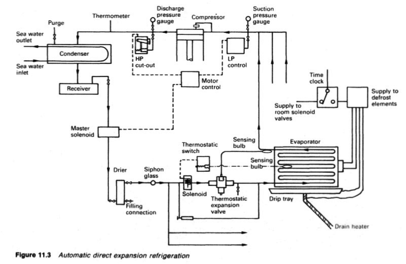
Figure : Automatic direct expansion refrigeration
Each cold compartment has a thermostatic expansion valve, which acts as
the regulator through which the correct amount of refrigerant is passed.
On large systems a master solenoid may be fitted. If the compressor stops
due to a fault, the master solenoid will close to prevent flooding by liquid
refrigerant and possible compressor damage.
The sketch is for a three compartment system but shows only the detail of
one. Each room has a solenoid, regulator and evaporator. Air blown through
the evaporator coils acts as the secondary refrigerant. Regular defrosting by
means of electric heating elements keeps the evaporator free from ice. The
automatic defrost time switch de-energizes the solenoids to shut down the
system and diverts electrical current to the heaters, for a set period.
System components:
The components described below may be found in refrigeration.
Compressors :
Refrigeration compressors are usually either reciprocating, or of the rotary
screw displacement type. Centrifugal and rotary vane compressors have also
been used.....more
Evaporators:
In the direct expansion system, shown in Figure 11,3, evaporation takes place
in air coolers consisting of pipe grids, plain or finned, enclosed in a closely
fitting casing, through which air.....
Expansion valves
:
The expansion valve is the regulator through which the refrigerant passes from
the high pressure side of the system to the low pressure side. The pressure drop
causes the evaporating temperature of the refrigerant to fall below that of the
evaporator. Thus, for example, the refrigerant can be boiled off by an
evaporator temperature of 18°C because the pressure drop brings the
evaporating temperature of the refrigerant down to say 24°C ..... more
Pipelines and auxiliary equipment
Refrigerant piping may be of iron, steel, copper or their alloys but copper and brass should not be used in contact with Refrigerant
The design of piping for refrigerating purposes differs a little from other shipboard systems in that the diameter of the piping is determined principally by the permissible pressure drop and the cost of reducing this.
However, any pressure drop in refrigerant suction lines demands increased power input per unit of refrigeration and decreases the capacity of the plant. Pressure drop in these lines should be kept to a minimum. To ensure continuous oil return, horizontal lines are usually dimensioned to give a minimum gas velocity of 230m/min and vertical risers to give 460 m/min. The pressure drop normally considered allowable is that equal to about 1°C change in saturated refrigerant temperature. This means a very small loss in low temperature systems as the pressure change at 244 K for a one degree saturation temperature change, is only one half of that consequent upon the same temperature change at 278K.
Horizontal pipelines should be pitched downstream to induce free draining and where the compressor is 10 m above the evaporator level, U-traps should be provided in vertical risers. Welding, or in the case of non-ferrous piping, soldering and brazing, are practically universal in pipe assembly, and except where piping is connected to removable components of the system, flanges are rarely used.
Summarized below various refrigeration system components, working process and maintenance guideline:
- Automatic direct expansion refrigeration- vapour compression
The basic components of any refrigeration system (Figure 11.1) working on the
vapour compression cycle, are the compressor, condenser, expansion valve,
evaporator and the refrigerant fluid which is alternately vaporized and liquefied
during the refrigeration cycle. The temperature at which a fluid boils or
condenses, is known as the saturation temperature and varies with pressure....more
-
Choice of refrigerants
Theoretically, almost any liquid can be used as a refrigerant if its pressure/temperature relationship is suitable for the conditions. Although no perfect refrigerant is known, there are certain factors which determine a refrigerant's desirability for a particular duty and the one selected should possess as many as possible of the following
characteristics.....more
-
Refrigeration systems - Chamber cooling arrangements
To avoid having an extended refrigeration circuit for cargo cooling, a brine system can be used. The brine is cooled by the evaporator and in turn cools grids or batteries. Grids provide cooling which relies on convection and conduction but air circulated through brine batteries provides a positive through cooling effect.
.....more
-
Refrigeration system components
Marine condensers are generally of the shell and tube type, designed for high pressures. There may a few coil-in-casing or other types still in use. The coolant passes through the tubes with refrigerant condensing on the outside......more
-
Refrigeration system compressors
Refrigeration compressors are usually either reciprocating, or of the rotary
screw displacement type. Centrifugal and rotary vane compressors have also
been used.....more
-
Refrigeration systems expansion valves
The expansion valve is the regulator through which the refrigerant passes from the high pressure side of the system to the low pressure side. The pressure drop causes the evaporating temperature of the refrigerant to fall below that of the evaporator. .....more
- Monitoring instruments,CO2 measurement & Heat leakage and insulation test
All necessary cargo temperature readings are obtained on modern reefers and container ships on a data logger which makes an automatic record. The temperatures and pressures relating to refrigerant gas and liquid, cooling water, brine and the ambient are also required. Most of these are obtained from direct reading instruments.
.....more
- Marine condenser assembly
The temperature of the refrigerated spaces with a direct expansion system is controlled between limits through a thermostatic switch and a solenoid valve which is either fully open to permit flow of refrigerant to the room evaporator, or closed to shut off flow. The solenoid valve is opened when the sleeve moving upwards due to the magnetic coil hits the valve spindle tee piece and taps the valve open.....more
- Comparison between refrigerants R717 ammonia & R744 carbon dioxide
The ammonia used for refrigeration systems based on the use of a compressor,
condenser, expansion valve and an evaporator (Figure 11.2) is dry (anhydrous)
in that there is no water in solution with it. It has the chemical formula NH3 but
as a refrigerant, it is coded with the number R717....more
-
Container cooling system
The air is cooled either by brine or direct expansion batteries and the containers are arranged so that one cooler can maintain a stack of containers at a given temperature. The temperature of the return air duct for each container is monitored.....more
Home page||Cooling ||Machinery||Services ||Valves ||Pumps ||Auxiliary Power ||Propeller shaft ||Steering gears ||Ship stabilizers||Refrigeration||Air conditioning ||Deck machinery||Fire protection||Ship design
||Home ||
General Cargo Ship.com provide information on cargo ships various machinery systems -handling procedures, on board safety measures and some basic knowledge of cargo ships that might be useful for people working on board and those who working in the terminal. For any remarks please
Contact us
Copyright © 2010-2016 General Cargo Ship.com All rights reserved.
Terms and conditions of use
Read our privacy policy|| Home page||