
Home page||Refrigeration system||
Function of Reciprocating compressors in a refrigeration circuit
Refrigeration compressors are usually either reciprocating, or of the rotary
screw displacement type. Centrifugal and rotary vane compressors have also
been used.
Function of Reciprocating compressors
Reciprocating compressors for systems cooling domestic store rooms are
usually of the vertical in-line type. The larger reciprocating compressors
(Figure 11.4) have their cylinders arranged in either V or W formation with 4,6,
8, 12 or even 16 cylinders.
Compressor speeds have been increased
considerably over the years from 500 rev/min to the high speed of 1500 to
2000 rev/min. The stroke/bore ratio has diminished to the point of becoming
fractional because of improvements in valve design and manufacture.
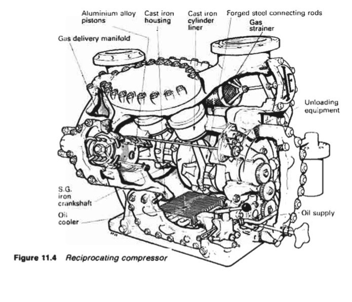
Figure :Reciprocating compressor
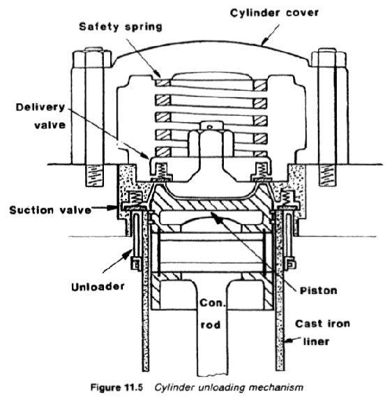
Figure : Cylinder unloading mechanism
Provision is made for unloading cylinders during starting and for
subsequent load control, by holding the suction valves off their seats (Figure
11.5) by suitable oil-pressure operated mechanisms. With this control the
compressors can be run at constant speed which is an advantage with a.c.
motors.
A bellows device, actuated by suction pressure can serve to cut out one or
more cylinders. Thus a falling suction pressure, indicating a reduced load on the
system, can be used to reduce automatically the number of working cylinders
to that required to deal with the existing load. Nearly all compressors of this
type are fitted with plate type suction and delivery valves, whose large diameter
and very small lifts offer the least resistance to the flow of refrigerant gas.
Each crank of the spheroidal graphite cast iron crankshaft for the W
configuration compressor shown carries four bottom ends. The aluminium
alloy pistons operate in cast iron liners, which are honed internally. Piston rings
may be of plain cast iron but special rings having phosphor-bronze inserts are
sometimes fitted. These assist when running in. Connecting rods are H section
steel forgings with white metal lined steel top end bushes.
Liners are of high
tensile cast iron and the crankcase and cylinders comprise a one-piece iron
casting. The two throw crankshaft is of spheroidal graphite cast iron. Each
throw carries four bottom ends as mentioned above but in other machines the
number of banks of cylinders may be less. Main bearings are white metal lined
steel shells.
Gas from the evaporator passes through a strainer housed in the suction
connection of the machine. This is lined with felt to trap scale and impurities
scoured from the system by the refrigerant particularly during the running-in
period, Freons are searching liquids, being similar to carbon tetrachloride. they
tend to clean the circuit but the impurities will cause problems unless removed
by strainers. Any oil returning with the refrigerant drains to the crankcase
through flaps at the side of the cylinder space.
The valve assembly is shown in Figure. 11.5 in more detail. The delivery
valve is held in place by a safety spring which is fitted to allow the complete
valve to lift in the event of liquid carry over to the compressor. The delivery
valve is an annular plate with its inside edge seated on the mushroom section
and its outside edge on the suction valve housing. The suction valve passes gas
from the suction space around the cylinder.
The control system includes a high pressure cut-out but a safety bursting
disc is also fitted between the compressor discharge and the suction. This may
be of nickel with a thickness of 0.05 mm. A ruptured disc is indicated by suction
and discharge pressures equalizing.
Shaft seal
Where motor and compressor casings are separate, a mechanical seal is fitted
around the crankshaft at the drive end of the crankcase. This prevents leakage
of oil and refrigerant from the crankcase. The type shown (Figure. 11,6)
consists of a rubbing ring with an oil hardened face against which the seal
operates. The seal is pressed on to the face by the tensioning spring and being
attached to bellows, it is self-adjusting. The rubbing ring incorporates a
neoprene or duprene ring which seals it to the shaft.
The mechanical seal is lubricated from the compressor system and can give
trouble if there is insufficient or contaminated oil in the machine. Undercharge
may be caused by seal leakage (sometimes due to oil loss). When testing the
seal for gas leakage, the shaft should be turned to different positions if the leak
is not apparent.
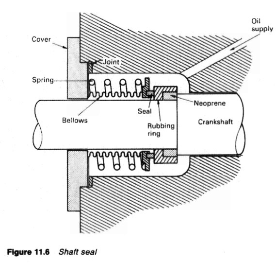
Figure : Shaft seal
Lubrication
Oil is supplied to the bearings and crankshaft seal by means of a gear pump
driven from the crankshaft. The oil is filtered through an Auto-Klean strainer
and/or an externally mounted filter with isolating valves. A pressure gauge
and sight glass are fitted and protection against oil failure is provided by a
differential oil pressure switch. Oil loss from the compressor is sometimes the
result of it being carried into the system by the refrigerant.
Oil pressure is about 2 bar above crankcase pressure and the differential oil
pressure switch is necessary to compare oil pressure with that of the gas in the
crankcase. There is a relief valve in the oil system set to about 2.5 bar above
crankcase pressure.
Cylinder walls are splash lubricated and some of the oil is carried around
with the refrigerant. If oil and refrigerant are miscible (i.e. if they form a mutual
solution) the oil tends to return via the circuit to the crankcase. When the
refrigerant is not miscible with the oil, the latter may be precipitated in the
system, usually in the evaporator. A float controlled oil trap (Figure. 11.7) may
be fitted or an automatic drain for the evaporator.
Oil must have a low pour point (additives are used) and with freons a
wax-free oil is necessary to avoid precipitation of wax at low temperatures.
Oil separators
Oil separators (Figure 11.7) of the impingement type, may be fitted in hot gas
discharge lines from the compressor. The type shown, is a closed vessel fitted
with a series of baffles or a knitted wire mesh through which the oil-laden
vapour passes. The reduction in velocity of the vapour as it enters the larger
area of the separator allows the oil particles, which have greater momentum, to
impinge on the baffles. The oil then drains by gravity to the bottom of the
vessel where a float valve controls flow to the compressor crankcase.
The chief disadvantage of separators placed in the hot gas discharge line is
the possibility of liquid refrigerant passing from the separator to the
compressor crankcase when the compressor is stopped. In order to minimize
this risk, the separators should be placed in the warmest position available. It is
good practice to drain the oil from the separator into a receiver containing
heating elements, where the liquid refrigerant boils off to the compressor
suction line and allows the oil to drain to the compressor crankcase through a
float valve.
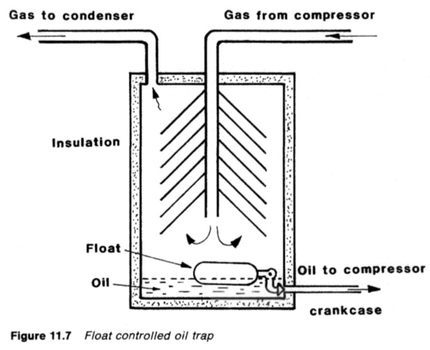
Figure : Float controlled oil trap
Oil rectifier
Some refrigerants are miscible with the compressor lubricating oil which means
that the two substances form a mutual solution. Because oil carry over does
occur, the miscibility is actually beneficial because the oil tends to be taken
around the refrigeration circuit and back to the compressor, by the refrigerant.
If the oil and refrigerant are not miscible, as is the case with oil and CO2, then
there may be a loss of lubricant from the compressor sump and accumulation in
the system. With CO2 the oil collected in the evaporator and was drained off
regularly by hand, then returned to the compressor after being strained. The oil
rectifier (Figure 11.8) can be fitted to drain oil from the evaporator,
automatically, and return it to the compressor.
The oil is automatically bled from the evaporator to a heat exchanger in
which liquid refrigerant mixed with the oil is vaporized. The heat for
vaporizing the refrigerant is obtained by passing warm liquid refrigerant from
the condenser, through the heat exchanger. Vapour and oil are passed to the
compressor where the oil returns to the sump while the freon passes to the
compressor suction. The regulator is a thermostatically controlled valve which
operates in the same way as the expansion valve in the main system. It
automatically bleeds the oil from the evaporator so that the gas leaves the
rectifier heat exchanger in a superheated condition.
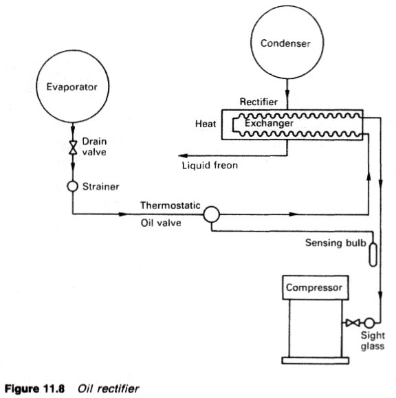
Figure : Oil rectifier
Summarized below various refrigeration system components, working process and maintenance guideline:
- Automatic direct expansion refrigeration- vapour compression
The basic components of any refrigeration system (Figure 11.1) working on the
vapour compression cycle, are the compressor, condenser, expansion valve,
evaporator and the refrigerant fluid which is alternately vaporized and liquefied
during the refrigeration cycle. The temperature at which a fluid boils or
condenses, is known as the saturation temperature and varies with pressure....more
-
Choice of refrigerants
Theoretically, almost any liquid can be used as a refrigerant if its pressure/temperature relationship is suitable for the conditions. Although no perfect refrigerant is known, there are certain factors which determine a refrigerant's desirability for a particular duty and the one selected should possess as many as possible of the following
characteristics.....more
-
Refrigeration systems - Chamber cooling arrangements
To avoid having an extended refrigeration circuit for cargo cooling, a brine system can be used. The brine is cooled by the evaporator and in turn cools grids or batteries. Grids provide cooling which relies on convection and conduction but air circulated through brine batteries provides a positive through cooling effect.
.....more
-
Refrigeration system components
Marine condensers are generally of the shell and tube type, designed for high pressures. There may a few coil-in-casing or other types still in use. The coolant passes through the tubes with refrigerant condensing on the outside......more
-
Refrigeration system compressors
Refrigeration compressors are usually either reciprocating, or of the rotary
screw displacement type. Centrifugal and rotary vane compressors have also
been used.....more
-
Refrigeration systems expansion valves
The expansion valve is the regulator through which the refrigerant passes from the high pressure side of the system to the low pressure side. The pressure drop causes the evaporating temperature of the refrigerant to fall below that of the evaporator. .....more
- Monitoring instruments,CO2 measurement & Heat leakage and insulation test
All necessary cargo temperature readings are obtained on modern reefers and container ships on a data logger which makes an automatic record. The temperatures and pressures relating to refrigerant gas and liquid, cooling water, brine and the ambient are also required. Most of these are obtained from direct reading instruments.
.....more
- Marine condenser assembly
The temperature of the refrigerated spaces with a direct expansion system is controlled between limits through a thermostatic switch and a solenoid valve which is either fully open to permit flow of refrigerant to the room evaporator, or closed to shut off flow. The solenoid valve is opened when the sleeve moving upwards due to the magnetic coil hits the valve spindle tee piece and taps the valve open.....more
- Comparison between refrigerants R717 ammonia & R744 carbon dioxide
The ammonia used for refrigeration systems based on the use of a compressor,
condenser, expansion valve and an evaporator (Figure 11.2) is dry (anhydrous)
in that there is no water in solution with it. It has the chemical formula NH3 but
as a refrigerant, it is coded with the number R717....more
-
Container cooling system
The air is cooled either by brine or direct expansion batteries and the containers are arranged so that one cooler can maintain a stack of containers at a given temperature. The temperature of the return air duct for each container is monitored.....more
Home page||Cooling ||Machinery||Services ||Valves ||Pumps ||Auxiliary Power ||Propeller shaft ||Steering gears ||Ship stabilizers||Refrigeration||Air conditioning ||Deck machinery||Fire protection||Ship design
||Home ||
General Cargo Ship.com provide information on cargo ships various machinery systems -handling procedures, on board safety measures and some basic knowledge of cargo ships that might be useful for people working on board and those who working in the terminal. For any remarks please
Contact us
Copyright © 2010-2016 General Cargo Ship.com All rights reserved.
Terms and conditions of use
Read our privacy policy|| Home page||