
Home page||Steering gears ||
Four ram gear with servo-controlled axial cylinder pumps
Variants of the servo-controlled swash plate axial cylinder pump (Figure below)
are capable of working at 210 bar. Each pump is complete with its own torque
motor, servo-valve, cut-off mechanism, shut-off valve and oil cooler. These
pumps are brought into operation as described earlier and an idle pump is
prevented from motoring.
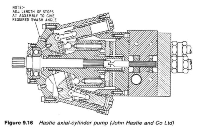
Figure : Hastie axial-cylinder pump (John Hastie and Co Ltd)
The rotating assembly of the pump, which consists of cylinder, nine pistons,
valve plate, slippers, slipper plate and retaining ring, is manufactured from ENS
steel, which is finally machined, heat treated and then hardened for long wear.
The nine pistons are fitted with return springs. The casing and covers are of
nodular cast iron.
The main valve block is of ENS steel and houses five check
valves, main pump relief valve, boost and servo-relief valves, boost gear pump
and servo-gear pumps. Piping from the valve block supplies the servo pistons
via the servo valve. The main drive is through a splined shaft to the cylinder
body of the pump. The pump swash plate is actuated by two servo cylinders
which receive oil at the desired pressure through a directional servo-valve.
The
servo-valve is displaced initially by the torque motor acting on the input signal
demand and is returned to the neutral position by the hunting linkage
connected to the swash plate. The hunting action is achieved through the
application of a simple lever system connecting input and displacement
servo-valve and the hunting action from the pump swash plate angle. This
allows for a very fast response.
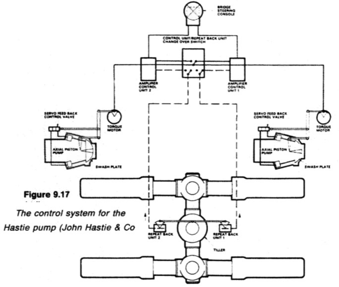
Figure : The control system for the Hastie pump (John Hastie & Co.
Ltd)
The control system is shown in Figure 9.17. As will be seen, a torque motor,
receiving the appropriate signal from the bridge through an amplifier unit
actuates the floating lever, putting the pumps on stroke in response. The
hunting action of the floating lever is no longer required as the normal control
of the steering gear from the bridge is by electric signal.
The signal is directed
to the torque motor which operates the servo valve that in turn controls the
pump. When the steering gear has attained the required rudder angle, the
electric feed back unit connected directly to the rudder-stock cancels the input
signal to the control amplifier, and the steering gear is held at that angle until
another rudder movement is required.
This form of control eliminates the need for mechanical linkage and hunting
gear on the steering gear.
Later modifications
The Amoco Cadiz disaster focused attention on the fact that failure of the
common hydraulic pipe system of a four ram steering gear with duplicated
power units, could result in rapid discharge of oil from the circuit and loss of
steering capability.
Four ram or double vane type gears with duplicated
hydraulic circuits, as well as duplication of pumps, were developed. This
arrangement cannot, however, be operated with both pumps running and the
duplicated hydraulic circuits isolated from each other. The systems have to be
connected in common for operation with both pumps. Either pump can provide
hydraulic power for the combined circuit or for an isolated half, with the bypass
open on the other part.
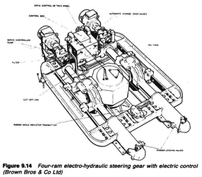
Figure : Four ram electro hydraulic steering gear with electric control
Figure above illustrates a four ram gear which complies with the International
Convention for the Safety of Life at Sea (SOLAS) regulations (1974, amended
1981) relating to tankers, chemical tankers or gas carriers of lOOOOgt and
upwards (see especially Chapter 11-1 Regulation 29, Paragraph 16).
Two main power and servo-power units draw from a two-compartment
tank fitted with oil level switches arranged at three levels. Level 1 gives an
initial alarm following loss of oil from either system. In normal operation one or
The Hastie-Brown split system, shown here in split operation,
is arranged to give two ram operation automatically in the event of loss of
fluid from one system both power units provide hydraulic power to all four rams. Continued loss of
oil initiates one or both of the level 2 switches. These energize their respective
solenoid operated servo valves, causing the combined isolating and bypass
valves to operate, splitting the system such that each power unit supplies two
rams only. At the same time if one power unit is stopped it is automatically
started.
Further loss of oil, and the system on which it is occurring will operate one of
the level 3 switches. This will close down the power units on the faulty side.
Steering then continues, uninterrupted but at half the designed maximum
torque on the sound system. The defective system is out of action and isolated.
Summarized below various ship steering gears general guideline:
- Ship Steering gear failures and safeguards
The hydraulic circuit incorporates an arrangement of stop and bypass valves in the chest VC, which enable the gear to be operated on all four or on any two adjacent cylinders but not with two diagonally disposed cylinders.
......
- Four-ram electro-hydraulic steering gear mechanism
The hydraulic circuit incorporates an arrangement of stop and bypass valves in the chest VC, which enable the gear to be operated on all four or on any two adjacent cylinders but not with two diagonally disposed cylinders.
......
- Enclosed hunting gear
The light construction of the combined control and hunting gears is possible
because the forces concerned are moderate. The self-contained unit is
self-lubricating, and contained in an oil-tight case.
......
- Ship steering control mechanism- use of Hydraulic telemotor
The telemotor has become, on many vessels, the stand-by steering control
mechanism, used only when the electric or automatic steering fails. It comprises
a transmitter on the bridge and a receiver connected to the steering gear
variable delivery pump, through the hunting gear.
......
- Two-ram electro-hydraulic steering gear with variable
delivery pumps
An arrangement of a two-ram steering gear with variable
delivery pumps may have a torque capacity of 120-650 kNm.
The cylinders for this gear are of cast steel but the rarns comprise a one-piece
steel forging with integral pins to transmit the movement through cod pieces
which slide in the jaws of a forked tiller end.
......
- Rudder carrier bearing & Steering gear
The rudder carrier bearing takes the weight of the rudder on a
grease lubricated thrust face. The rudder stock is located by the journal
beneath, also grease lubricated
......
- Small hand and power gears - Ship steering systems
A simpler variant of the electro-hydraulic gear, for small ships requiring rudder
torques below say, 150 kNm
......
- Four ram gear with servo-controlled axial cylinder pumps
Variants of the servo-controlled swash plate axial cylinder pump
are capable of working at 210 bar. Each pump is complete with its own torque
motor, servo-valve, cut-off mechanism, shut-off valve and oil cooler.
......
- Vane type gear - provides security of four ram steering gear
These may be regarded as equivalent to a two-ram gear, with torque capacities
depending on size. An assembly of two rotary vane gears, one above the other,
provides the security of a four ram gear.
......
- Details of two ram hydraulic steering gear arrangement
When the main pumps are at no-stroke, the auxiliary pumps dischar.
to the reservoir via a pressure-limiting valve PC20, set at 20 bar, and to t
pump casings. When the main pumps are on-stroke, the auxiliary pump
discharge to the main pump suction.
......
Home page||Cooling ||Machinery||Services ||Valves ||Pumps ||Auxiliary Power ||Propeller shaft ||Steering gears ||Ship stabilizers||Refrigeration||Air conditioning ||Deck machinery||Fire protection||Ship design
||Home ||
General Cargo Ship.com provide information on cargo ships various machinery systems -handling procedures, on board safety measures and some basic knowledge of cargo ships that might be useful for people working on board and those who working in the terminal. For any remarks please
Contact us
Copyright © 2010-2016 General Cargo Ship.com All rights reserved.
Terms and conditions of use
Read our privacy policy|| Home page||