
Home page||Steering gears ||
Detailed description of two ram hydraulic steering gear
With reference to the sketch (Figure 9.11), the duplicate power units PUl and
PU2, each have a continuously running electric motor driving, through a
flexible coupling a variable delivery axial-cylinder pump and auxiliary pumps,
A1, A2. The latter draw filtered oil from the reservoir T and discharge through
a 10 micron filter FlO to supply oil at constant pressure to the servo-controls
SG to the automatic change-over valves CO, to maintain a flow of cool oil
through the main pump casings and to make up any oil loss from the main
system.
When the main pumps are at no-stroke, the auxiliary pumps dischar.
to the reservoir via a pressure-limiting valve PC20, set at 20 bar, and to t
pump casings. When the main pumps are on-stroke, the auxiliary pump
discharge to the main pump suction.
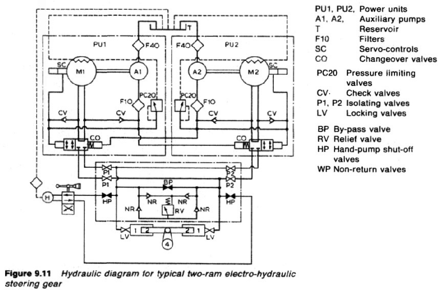
Figure :Hydraulic diagram for typical two ram electro hydraulic steering gear
Figure 9.11 Hydraulic diagram for typical two-ram electro-hydraulic
steering gear
PU1, PU2, Power units PC20 Pressure limiting BP By-pass valve
A1, A2, Auxiliary pumps valves RV Relief valve
T Reservoir CV Check valves HP Hand-pump shut-off
F10 Filters P1, P2 Isolating valves valves
SC Servo-controls LV Locking valves WP Non-return valves
CO Changeover valves
300 Steering gears
A main pump may be brought into operation at any position of the gear,at
any time, by starting the motor. The servo-operated automatic change-over
valves (Figure 9.12) are held in the bypass condition by a spring, while the
associated pump is at rest.
When a pump is started, the auxiliary pump pressure
builds up, overcomes the spring, closes the bypass and connects the main pump
to the hydraulic system. Thus, the main pump starts in the unloaded condition
it cannot be motored when idle by cross pressure flow and load is held off until
the electric motor high starting current has reduced to running level When a
pump is stopped, the spring returns the valve to the bypass condition. The
spring end of the valve is connected to the constant pressure line and,
obviate hydraulic locking, the spring chamber has a bleed line.
From the
automatic change-over valves CO the main pump discharge passes to the
pump isolating valves, Pi and P2, and to the cylinders, through the locking
valves LV. These valves are incorporated in a group valve chest so arranged as
to provide cross-connections with the bypass valve BP, relief valve RV and the
emergency hand pump shut-off valves, HP, with appropriate non-return valves
NR.
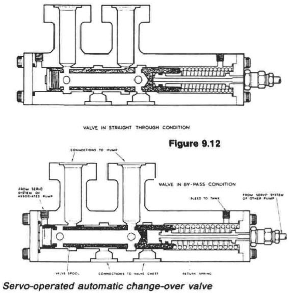
Figure : Servo operated automatic change over valve
In open water it is usual to have one power unit in use. If quicker response is
required from the gear, two units may be run simultaneously to double oil flow
and increase speed of operation.
Normally the gear is controlled from the bridge through an electric
telemotor and local control box, but a local control handwheel is also provided
as is a means of communication with the bridge.
Summarized below various ship steering gears general guideline:
- Ship Steering gear failures and safeguards
The hydraulic circuit incorporates an arrangement of stop and bypass valves in the chest VC, which enable the gear to be operated on all four or on any two adjacent cylinders but not with two diagonally disposed cylinders.
......
- Four-ram electro-hydraulic steering gear mechanism
The hydraulic circuit incorporates an arrangement of stop and bypass valves in the chest VC, which enable the gear to be operated on all four or on any two adjacent cylinders but not with two diagonally disposed cylinders.
......
- Enclosed hunting gear
The light construction of the combined control and hunting gears is possible
because the forces concerned are moderate. The self-contained unit is
self-lubricating, and contained in an oil-tight case.
......
- Ship steering control mechanism- use of Hydraulic telemotor
The telemotor has become, on many vessels, the stand-by steering control
mechanism, used only when the electric or automatic steering fails. It comprises
a transmitter on the bridge and a receiver connected to the steering gear
variable delivery pump, through the hunting gear.
......
- Two-ram electro-hydraulic steering gear with variable
delivery pumps
An arrangement of a two-ram steering gear with variable
delivery pumps may have a torque capacity of 120-650 kNm.
The cylinders for this gear are of cast steel but the rarns comprise a one-piece
steel forging with integral pins to transmit the movement through cod pieces
which slide in the jaws of a forked tiller end.
......
- Rudder carrier bearing & Steering gear
The rudder carrier bearing takes the weight of the rudder on a
grease lubricated thrust face. The rudder stock is located by the journal
beneath, also grease lubricated
......
- Small hand and power gears - Ship steering systems
A simpler variant of the electro-hydraulic gear, for small ships requiring rudder
torques below say, 150 kNm
......
- Four ram gear with servo-controlled axial cylinder pumps
Variants of the servo-controlled swash plate axial cylinder pump
are capable of working at 210 bar. Each pump is complete with its own torque
motor, servo-valve, cut-off mechanism, shut-off valve and oil cooler.
......
- Vane type gear - provides security of four ram steering gear
These may be regarded as equivalent to a two-ram gear, with torque capacities
depending on size. An assembly of two rotary vane gears, one above the other,
provides the security of a four ram gear.
......
- Details of two ram hydraulic steering gear arrangement
When the main pumps are at no-stroke, the auxiliary pumps dischar.
to the reservoir via a pressure-limiting valve PC20, set at 20 bar, and to t
pump casings. When the main pumps are on-stroke, the auxiliary pump
discharge to the main pump suction.
......
Home page||Cooling ||Machinery||Services ||Valves ||Pumps ||Auxiliary Power ||Propeller shaft ||Steering gears ||Ship stabilizers||Refrigeration||Air conditioning ||Deck machinery||Fire protection||Ship design
||Home ||
General Cargo Ship.com provide information on cargo ships various machinery systems -handling procedures, on board safety measures and some basic knowledge of cargo ships that might be useful for people working on board and those who working in the terminal. For any remarks please
Contact us
Copyright © 2010-2016 General Cargo Ship.com All rights reserved.
Terms and conditions of use
Read our privacy policy|| Home page||