
Home page||Propeller shaft ||
Controllable pitch propellers
Controllable pitch propellers are normally fitted to a flanged tailshaft as the operating mechanism is housed in the propeller boss. As its name implies, it is possible to alter the pitch of this type of propeller to change ship speed or to adjust to the prevailing resistance conditions. This change in pitch is effected by rotating the blades about their vertical axes, either by hydraulic or mechanical means.
A shaft generator can be driven at constant speed while allowing at the same time a change of ship's speed through the propeller. Since it is normally possible to reverse the pitch completely, this type of propeller is used with a uni-directional engine to give full ahead or astern thrust, when manoeuvring.
The most obvious application is for ferries or other vessels which regularly and frequently manoeuvre in and out of port. They are also used for double duty vessels, such as tugs or trawlers where the operating conditions for towing or for running free are entirely different.
One of the most widely used controllable pitch (c.p.) propellers is the KaMeWa, a hydraulically operated Swedish propeller first introduced in 1937. In this unit (Figures 8.28a and 8.28b) the blade pitch is altered by a servomotor piston housed within the hub body. The piston moves in response to the difference in oil pressure on its ends.
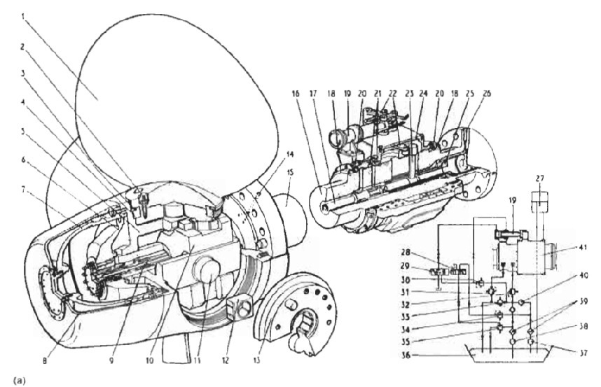
Figure : single-piston-servometer
Figure : single-piston-servometer-details
Oil flow to and from the servomotor is controlled by a slide valve in the piston rod; the slide valve is part of a hollow rod which passes through a hole bored in the propeller shaft and is mechanically operated by operating levers located in an oil distribution box. If the slide valve is moved aft, the valve ports are so aligned that oil under pressure flows along the hollow valve rod to the forward end of the piston, causing the piston to move in the same direction, until the ports are again in a neutral position.
When the valve is moved forward, the piston will move in a forward direction. When the piston moves, the crosshead with its sliding shoes moves with it. A pin on a crank pin ring, attached to each propeller blade, locates in each of the sliding shoes, so that any movement of the servomotor piston causes a pitch change simultaneously in the propeller blades.
Oil enters and leaves the hub mechanism via an oil distribution box mounted inside the ship on a section of intermediate shaft. Oil pressure of about 40 bar maximum in the single piston hub, is maintained by an electrically driven pump, which has a stand-by.
A spring loaded, inlet pressure regulating valve on the oil distribution box, controls the pressure in the high pressure chamber from where the oil passes to the hub mechanism via the hollow rod in the propeller shaft. Oil passes from the hub mechanism to the low pressure
chamber of the distribution box along the outside of the valve rod, A spring loaded back pressure regulating valve on the oil outlet, maintains a slight back pressure on the oil filled hub, when the vessel is underway. When in port this pressure is maintained by the static head of an oil tank mounted above the ship's waterline and connected to the oil distribution box.
The oil pressure in the hub is needed to balance outside pressure from the sea and so make leakage in either direction unlikely. The forward end of the valve rod connects to a T bar or key which is moved forward or aft by a sliding ring within the oil distribution box. (The T bar rotates with the shaft,) A servomotor mounted externally to the box is used to move the sliding ring through a yoke.
In the event of a failure in the servomotor, an external lever can be used to shift the valve rod manually and so control blade pitch. A powerful spring may be 6tted so that in the event of loss of hydraulic oil pressure, the blades will be moved towards the full ahead position. Forces on the blades tend to prevent the full ahead position from being attained and it may be necessary to slow the engine or even stop it, to allow the spring to act. The spring could be fitted to give a fail safe to astern pitch.
Some controllable pitch propellers are arranged to remain at the current setting if hydraulic oil loss occurs. Where a shaft alternator is installed, engine speed may remain constant as propeller pitch is altered for manoeuvring. Alternatively, propeller pitch and engine speed can be remotely controlled from a single lever known as a combinator. Any number of combinators may be installed in a ship. The combinator lever controls pitch and speed through cam-operated transmitters. These may be electrical or pneumatic devices,
Summarized below some of the basic procedure of marine propeller shaft :
- Propeller shaft materials and couplings
The intermediate shafting and the propeller shaft for a fixed propeller are of
solid forged ingot steel and usually with solid forged couplings. Shafts are
machined all over but of a larger diameter and smooth turned in way of the
bearings.
......
- Fixed pitch propeller
The normal method of manufacture for a fixed pitch propeller, is to cast the blades integral with the boss and after inspection and marking, to machine the
tapered bore and faces of the boss before the blades are profiled by hand with reference to datum grooves cut in the surfaces or with an electronically controlled profiling machine.
......
- Controllable pitch propeller
Controllable pitch propellers are normally fitted to a flanged tailshaft as the operating mechanism is housed in the propeller boss. As its name implies, it is possible to alter the pitch of this type of propeller to change ship speed or to adjust to the prevailing resistance conditions.
......
- Propeller thrust block
The main thrust block transfers forward or astern propeller
thrust to the hull and limits axial movement of the shaft. Some axial clearance is essential to
allow formation of an oil film in the wedge shape between the collar and the
thrust pads
......
- Propeller shaft gears and clutches
For medium-speed engine installations in large ships (as opposed to coasters or intermediate sized vessels) reduction gears are needed to permit engines and propellers to run at their best respective speeds. Their use also permits more than one engine to be coupled to the same propeller. Gearboxes are available from manufacturers in standard sizes.
......
- Propeller shaft check
The intention of good alignment is to ensure that bearings are correctly loaded
and that the shaft is not severely stressed. Alignment can be checked with
conventional methods, employing light and targets, laser or measurements
from a taut wire.
......
- Propeller shaft bearings check
The intermediate shafting between the tailshaft and main engine,
gearbox or thrustblock may be supported in plain, tilting pad or roller bearings.
......
- Oil lubricated stern tube
Progress from sea-water to early oil-lubricated stern tubes involved an
exchange of the wooden bearing in its bronze sleeve for a white metal
lined cast iron (or sometimes bronze) bush. Oil retention and exclusion of
sea water necessitated the fitting of an external face type seal.
......
- Water lubricated stern tube
The traditional stern bearing is water-lubricated and consists of a
number of lignum vitae staves held by bronze retaining strips, in a gunmetal
bush. Lignum vitae is a hardwood with good wear characteristics and is
compatible with water.
......
- Stern tube sealing arrangement
There are basically three sealing arrangements used for stern bearings. These are:
Simple stuffing boxes filled with proprietary packing material. Lip seals, in which a number of flexible membranes in contact with the
shaft, prevent the passage of fluid along the shaft.
& Radial face seals, in which a wear-resistant face fitted radially around the
shaft,
......
- Stern tube bearings
To avoid the necessity for drydocking when an examination of stern bearings
amid tailshaft is needed, split stern bearings were developed. A suitable
outboard sealing arrangement and design, permits the two halves of the
bearing to be drawn into the ship, exposing the shaft and the white metal
bearing.
......
Home page||Cooling ||Machinery||Services ||Valves ||Pumps ||Auxiliary Power ||Propeller shaft ||Steering gears ||Ship stabilizers||Refrigeration||Air conditioning ||Deck machinery||Fire protection||Ship design
||Home ||
General Cargo Ship.com provide information on cargo ships various machinery systems -handling procedures, on board safety measures and some basic knowledge of cargo ships that might be useful for people working on board and those who working in the terminal. For any remarks please
Contact us
Copyright © 2010-2016 General Cargo Ship.com All rights reserved.
Terms and conditions of use
Read our privacy policy|| Home page||