
Home page||Propeller shaft ||
Stern tube bearings -various type & functional guideline
Split stern bearings
To avoid the necessity for drydocking when an examination of stern bearings
amid tailshaft is needed, split stern bearings were developed. A suitable
outboard sealing arrangement and design, permits the two halves of the
bearing to be drawn into the ship, exposing the shaft and the white metal
bearing.
Glacier-Herbert stern bearing
In the Glacier-Herbert system (Figure 8.16) the two completely symmetrical
bearing halves are flanged along the horizontal centre line and held together by
bolts. The after end of the bearing carries a spherical support ring to which is
bolted the outboard seal housing.
The spherical support ring rests in a carrier
ring which is bolted to the after end of the stern frame boss. The forward end is
supported by a circular diaphragm which is bolted to a flange provided in the
stern frame casting. This diaphragm also acts as a carrier for the forward seal,
A series of axial bolts, fitted with Belleville washer packs to ensure virtually
constant loading of these bolts and those securing the spherical seating ring,
hold the diaphragm firmly in position. This arrangement permits sloped
alignment of the bearing to give full support to the drooping tailshaft.
Chocks
are used to hold the bearing positively in its final position. The arrangement is
such that it allows for the differential expansion of the bearing and its housing
without detracting from the rigidity of support at the forward end of the bearing.
The propeller shaft is flanged at the after end and the hub of the propeller is
bolted to the flange. On the inboard side there is a shroud around the spigot
projecting aft from the carrier ring. Two inflatable seals with individual air
supplies are fitted in the periphery of the spigot. These can be inflated to
provide a seal against inflow of water.
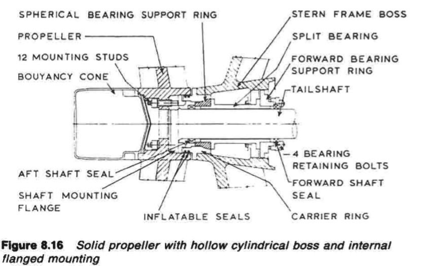
Figure :Solid propeller with hollow cylindrical boss and internal
flanged mounting
Sealing the stern bearing space permits work to be carried out on the stern
bearing and seals, without the necessity of drydocking. An alternative to using
the inflatable seals, is to apply a sealing bandage around the small gap at the
carrier ring flange.
The propeller shaft has two short rotating liners of chrome steel. The liner at
the after end is bolted to the propeller shaft flange. The inboard liner is fixed by
a clamping ring. These liners act as rubbing surfaces for the rubber lip seals.
The coupling at the forward end of the tailshaft may be of the SKF oil
injection type (i.e. muff coupling) described previously.
Ross-Turnbull split bearing
The Ross-Turnbull split stern bearing (Figure 8.17) has a bottom half bearing
which is chocked on to two horizontal fore and aft machined surfaces within
the stem frame boss. The whole bearing is held in position vertically by two
50 tonne Pilgrim type jacks, the chock thickness determining the bearing
height. These jacks also hold the top half of the bearing in place. Lateral
positioning of the bearing is by 30 tonne Pilgrim type jacks arranged on each
side of the bearing.
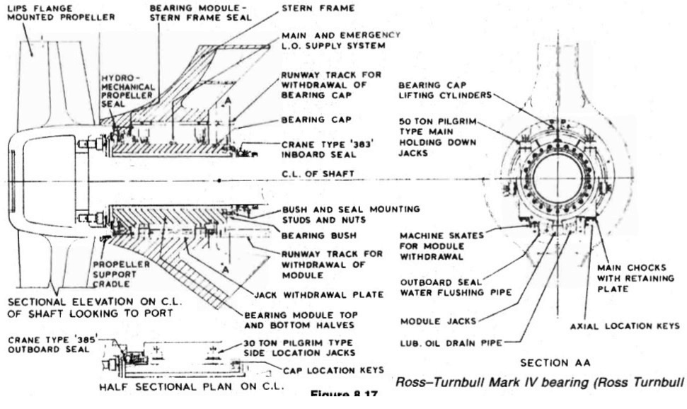
Figure : The Ross-Turnbull split stern bearing
A running track is arranged above the bearing to allow easy
transport of the top half. Skids are provided below the bearing to provide easy
transport of the bottom half. When removing the bearing bottom half, a jack is
first placed underneath it to lift it free of its chocks. The chocks are removed and
skates are placed under the bottom half bearing. With the chocks out, the
assembly is lowered until the propeller rests on the shroud or support cradle,
which is part of the stern frame boss.
Further lowering of the jacks, brings the
bottom half away from the tailshaft until its weight is taken by the skates
resting on the skids. The jacks are removed and the bottom half bearing is
brought forward on the skates together with the seal face and the bellows
section of the outboard seal.
Summarized below some of the basic procedure of marine propeller shaft :
- Propeller shaft materials and couplings
The intermediate shafting and the propeller shaft for a fixed propeller are of
solid forged ingot steel and usually with solid forged couplings. Shafts are
machined all over but of a larger diameter and smooth turned in way of the
bearings.
......
- Fixed pitch propeller
The normal method of manufacture for a fixed pitch propeller, is to cast the blades integral with the boss and after inspection and marking, to machine the
tapered bore and faces of the boss before the blades are profiled by hand with reference to datum grooves cut in the surfaces or with an electronically controlled profiling machine.
......
- Controllable pitch propeller
Controllable pitch propellers are normally fitted to a flanged tailshaft as the operating mechanism is housed in the propeller boss. As its name implies, it is possible to alter the pitch of this type of propeller to change ship speed or to adjust to the prevailing resistance conditions.
......
- Propeller thrust block
The main thrust block transfers forward or astern propeller
thrust to the hull and limits axial movement of the shaft. Some axial clearance is essential to
allow formation of an oil film in the wedge shape between the collar and the
thrust pads
......
- Propeller shaft gears and clutches
For medium-speed engine installations in large ships (as opposed to coasters or intermediate sized vessels) reduction gears are needed to permit engines and propellers to run at their best respective speeds. Their use also permits more than one engine to be coupled to the same propeller. Gearboxes are available from manufacturers in standard sizes.
......
- Propeller shaft check
The intention of good alignment is to ensure that bearings are correctly loaded
and that the shaft is not severely stressed. Alignment can be checked with
conventional methods, employing light and targets, laser or measurements
from a taut wire.
......
- Propeller shaft bearings check
The intermediate shafting between the tailshaft and main engine,
gearbox or thrustblock may be supported in plain, tilting pad or roller bearings.
......
- Oil lubricated stern tube
Progress from sea-water to early oil-lubricated stern tubes involved an
exchange of the wooden bearing in its bronze sleeve for a white metal
lined cast iron (or sometimes bronze) bush. Oil retention and exclusion of
sea water necessitated the fitting of an external face type seal.
......
- Water lubricated stern tube
The traditional stern bearing is water-lubricated and consists of a
number of lignum vitae staves held by bronze retaining strips, in a gunmetal
bush. Lignum vitae is a hardwood with good wear characteristics and is
compatible with water.
......
- Stern tube sealing arrangement
There are basically three sealing arrangements used for stern bearings. These are:
Simple stuffing boxes filled with proprietary packing material. Lip seals, in which a number of flexible membranes in contact with the
shaft, prevent the passage of fluid along the shaft.
& Radial face seals, in which a wear-resistant face fitted radially around the
shaft,
......
- Stern tube bearings
To avoid the necessity for drydocking when an examination of stern bearings
amid tailshaft is needed, split stern bearings were developed. A suitable
outboard sealing arrangement and design, permits the two halves of the
bearing to be drawn into the ship, exposing the shaft and the white metal
bearing.
......
Home page||Cooling ||Machinery||Services ||Valves ||Pumps ||Auxiliary Power ||Propeller shaft ||Steering gears ||Ship stabilizers||Refrigeration||Air conditioning ||Deck machinery||Fire protection||Ship design
||Home ||
General Cargo Ship.com provide information on cargo ships various machinery systems -handling procedures, on board safety measures and some basic knowledge of cargo ships that might be useful for people working on board and those who working in the terminal. For any remarks please
Contact us
Copyright © 2010-2016 General Cargo Ship.com All rights reserved.
Terms and conditions of use
Read our privacy policy|| Home page||