
Home page||Propeller shaft ||
Ships propeller Shaft checks general guideline
Propeller shaft, tail shaft The aftermost section of the propulsion shafting in the stern
tube in single screw ships and in the struts of multiple screw ships to which the propeller
is fitted.
Propulsion shafting constitutes a system of revolving rods that transmit power and motion from
the main drive to the propeller. The shafting is supported by an appropriate number of
bearings.
The intention of good alignment is to ensure that bearings are correctly loaded
and that the shaft is not severely stressed. Alignment can be checked with
conventional methods, employing light and targets, laser or measurements
from a taut wire. There is, however, a continuity problem because the line of
sight or taut wire cannot extend over the full length of an installed shaft. There
is no access to that part of the shaft within the stern tube and access is difficult
in way of the propulsion machinery. Results are also uncertain unless the vessel
is in the same condition with regard to loading and hull temperatures as when
the shaft system was installed or previously checked.
The method of jacking (Figure 1) to assess correct bearing loads, is used as
a realistic means of ensuring that statically, the shaft installation is satisfactory.
In simple terms the load on each bearing can be stated as the total weight of the
shaft divided by the number of bearings. The figure for designed load is
normally given in a handbook with the usual permitted deviation of plus or
minus 50%. The permitted variation may be less for some bearings.
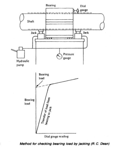
Figure 1: Method of checking bearing load
The procedure involves the use of hydraulic jacks placed on each side of the
bearing, to lift the shaft just clear. A dial gauge fixed to the bearing indicates
lift. Hydraulic pressure, exerted by the jacks, registers the load on the bearing.
Figure 8.1 Method for checking bearing load by jacking (R. C. Dean)
A plot of lift and load made while hydraulically lifting the shaft, shows a
distinctive pattern, due to the elasticity of the steel and removal of deformation
from the bearing.
As the hydraulic jack pressures are raised from zero, the concentrated
loading initially causes deformation of the shaft. Only after the journal section
has been bowed up out of shape to some degree, and the bearing material
resumes its relaxed primary shape, does the sagging centre part of the journal
lift clear and out of contact with the bearing. The plot shows that the dial
gauges register upward movement as soon as the shaft is pushed out of shape
by increasing hydraulic pressure. The curve takes a different shape as the shaft
lifts clear.
If the jacking is taken too far, then adjacent bearings gradually become
unloaded and the plot is affected by a change in the elastic system. To guard
against this, dial gauges are fixed on adjacent bearings to ensure that the lift is
limited to the bearing that is being checked.
Strain gauges
Shaft stress is sometimes monitored in service, by fitting strain gauges on the
shaft. These register alternating surface stretch and compression as the shaft
rotates.
Change of engine position
The conventional midships position for the engines of older vessels, with the
exception of tankers, was based on low engine power and strong hull
construction. Shafts were long, but being of moderate diameter, were able to
flex with the hull as loading or other conditions changed (and in heavy
weather).
A loading or ballast condition which changed hull shape and shaft
alignment to an unusual degree, sometimes caused higher temperature in some
bearings due to uneven load distribution. Shaft stress was the hidden factor.
The trend towards higher engine powers and the positioning of engines aft,
gave rise to large diameter, short length shafts of increased stiffness.
Excessive
vibration and resulting damage in many dry cargo and container vessels is a
common feature as a result. Hull detuners intended to reduce vibration have
been fitted in steering gear compartments but the improvement to many ships
seems to be marginal. Hull vibration seems to be less of a problem in ships with
one cargo compartment aft of the machinery space.
Establishing the shaft centre line
Optical (or laser) equipment can be used to establish the centre line of the
shafting system, to give a reference for cutting through bulkheads and
machining of the aperture in the stern frame. One method employs a telescope
with crosswires, set up on the shaft centre line at the forward end of the double
bottom engine platform with a plain cross wire target on the same axis at the
after end of the engine seating. With both in use, the centre of engine room and
aft peak bulkheads can be located and marked prior to cutting holes for the
shaft.
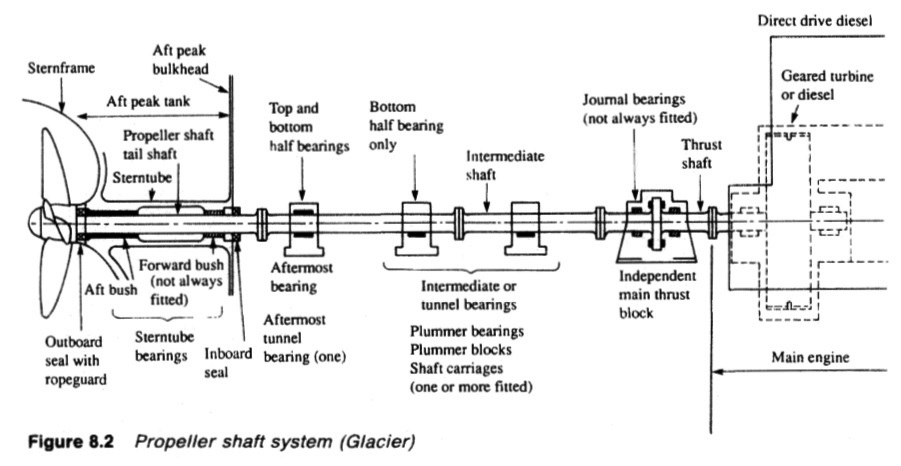
Figure : Propeller shaft system
The required centre of the aperture in the stern frame boss, can then be
found by line of sight, using a crosswire in an adjustable spider. Replacement of
the crosswire by a plug with a centre gives a location for the divider to be used
when marking off the boss for boring. Importantly, the telescope and crosswire
target method can also be used to check the accuracy of the boring operation,
work on the installation of the stern tube and siting of shaft bearings.
Some arrangements as for split stem tubes, involve the welding in of the boss and this
operation can be guided by constant checking with optical equipment.
Deviation while building
With the ship under construction still firmly supported, faults causing shaft
misalignment can and do occur. The stern tube aperture can be incorrectly
machined due to flexure of the boring bar or human error. Any contraction or
expansion of the hull as a result of temperature variation can conspire with
changes caused by welding of the hull to effect change of hull shape. The
welding in place of a fabricated stern tube requires constant checks to ensure
alignment is maintained. Some stern tube bearing failures have been traced to
alignment errors which should have been detected and remedied during
installation.
After fitting the stern tube and propeller shaft, the propeller is mounted. The
considerable weight of the propeller however, causes droop in the tailshaft and
potential edge loading of the stern tube bearing. Arching tends to lift the
inboard end of the propeller (or tail) shaft so that the next bearing forward
whether in the stern tube or beyond, would tend to be negatively loaded.
Deformation imposed by the propeller mass, remains even after installation of
the rest of the shaft system.
The remedy for edge loading due to propeller shaft droop, is to arrange for
the stern tube bearing to be slope bored or installed with a downward lie. Shaft
weight is then fully supported along the bearing surface.
After the ship has been launched, the immersed section of the heavily framed
stern with the propeller mass, being much less buoyant than the full hull further
forward, flexes downward. This emphasizes the droop of the propeller shaft
and resulting inherent misalignment. Downward flexing of the stem also
deforms the hull, changing the line of the tank top.
It was the normal practice to
install the intermediate shafting after the launch, when the ship assumed its
in-water shape. The shafting was installed from the tailshaft to the engine.
Optical equipment, as before, could be used to check the position of the
propeller shaft inboard flange and to locate the centres of plumber bearings.
Chocks for the shaft bearings are machined to the correct height.
Traditionally, the fairing of couplings has been used to align shafts and to
check the alignment of adjacent shaft sections. The fairing of couplings
involves the insertion of feelers between a pair of couplings to check that they
are parallel and the use of a straight edge or dial gauge, to ensure that they are
concentric. Incorrect alignment can result if it is assumed that shaft sections are
rigid; particularly with the heavy shaft sections for engines of high power.
Account must be taken of slight droop due to elasticity and overhanging
weight at each shaft flange. The natural deformation of shaft sections is taken
into account with rational alignment programmes and coupling conditions can
be used to position shaft sections and to check alignment. For this procedure,
pre-calculation is used to find the gap and sag that should exist between
couplings, when shaft alignment is correct.
Alignment deviation in service
Shaft line is continually changed through the lifetime of a ship, as the hull is
distorted by hog or sag due to different conditions of loading. The weight and
distribution of cargo, ballast, fuel and fresh water are all subject to change and
the changes are known from experiment to affect shaft alignment. (Incorrect
cargo discharge procedures and resulting excessive hull stresses have resulted
in ships actually breaking in two.)
High deck temperature in the tropics or low sea temperatures can cause
differential expansion and hogging of the hull. These types of change can alter
crankshaft deflection or shaft alignment readings which are taken even a few
hours apart. Heavy weather produces cyclic change of hull shape so that the
hull of a moderately sized ship can flex by as much as 150 mm. There are also
local factors which alter shaft alignment. Thus the forward tilt of a loaded
thrust block, and the lift of its after bearing, causes misalignment of the shaft
and possible uneven loading of gear teeth. A build-up of fluid film pressure in
bearings, as the shaft starts to rotate, lifts the shaft bodily. Sinkage of individual
piumber blocks could be another problem.
Fair curve alignment
The method of fair curve alignment (using a computer programme developed
at the Boston Navy Yard in 1954 and refined by others) accepts the changes of
line endured by the shaft system and seeks a compromise installation to suit the
varying conditions.
The initial calculation is to determine the load on each bearing, assuming all
bearings to be in a straight line. The computer programme then simulates the
raising of each bearing through a range and calculates, for each small change,
the increase of its own load and alteration in load on each of the other bearings.
The process is then repeated with a simulation of the lowering of each bearing
in turn with the computer rinding resultant load changes on the bearing in
question and the others. Influence numbers, in terms of load change for each
height variation, are calculated by this exercise for all bearings.
The data bank of influence numbers enables the effects of changes in
alignment from hull flexure and local factors to be found. All of the variables
described above can be assessed to determine the best compromise for shaft
installation.
Summarized below some of the basic procedure of marine propeller shaft :
- Propeller shaft materials and couplings
The intermediate shafting and the propeller shaft for a fixed propeller are of
solid forged ingot steel and usually with solid forged couplings. Shafts are
machined all over but of a larger diameter and smooth turned in way of the
bearings.
......
- Fixed pitch propeller
The normal method of manufacture for a fixed pitch propeller, is to cast the blades integral with the boss and after inspection and marking, to machine the
tapered bore and faces of the boss before the blades are profiled by hand with reference to datum grooves cut in the surfaces or with an electronically controlled profiling machine.
......
- Controllable pitch propeller
Controllable pitch propellers are normally fitted to a flanged tailshaft as the operating mechanism is housed in the propeller boss. As its name implies, it is possible to alter the pitch of this type of propeller to change ship speed or to adjust to the prevailing resistance conditions.
......
- Propeller thrust block
The main thrust block transfers forward or astern propeller
thrust to the hull and limits axial movement of the shaft. Some axial clearance is essential to
allow formation of an oil film in the wedge shape between the collar and the
thrust pads
......
- Propeller shaft gears and clutches
For medium-speed engine installations in large ships (as opposed to coasters or intermediate sized vessels) reduction gears are needed to permit engines and propellers to run at their best respective speeds. Their use also permits more than one engine to be coupled to the same propeller. Gearboxes are available from manufacturers in standard sizes.
......
- Propeller shaft check
The intention of good alignment is to ensure that bearings are correctly loaded
and that the shaft is not severely stressed. Alignment can be checked with
conventional methods, employing light and targets, laser or measurements
from a taut wire.
......
- Propeller shaft bearings check
The intermediate shafting between the tailshaft and main engine,
gearbox or thrustblock may be supported in plain, tilting pad or roller bearings.
......
- Oil lubricated stern tube
Progress from sea-water to early oil-lubricated stern tubes involved an
exchange of the wooden bearing in its bronze sleeve for a white metal
lined cast iron (or sometimes bronze) bush. Oil retention and exclusion of
sea water necessitated the fitting of an external face type seal.
......
- Water lubricated stern tube
The traditional stern bearing is water-lubricated and consists of a
number of lignum vitae staves held by bronze retaining strips, in a gunmetal
bush. Lignum vitae is a hardwood with good wear characteristics and is
compatible with water.
......
- Stern tube sealing arrangement
There are basically three sealing arrangements used for stern bearings. These are:
Simple stuffing boxes filled with proprietary packing material. Lip seals, in which a number of flexible membranes in contact with the
shaft, prevent the passage of fluid along the shaft.
& Radial face seals, in which a wear-resistant face fitted radially around the
shaft,
......
- Stern tube bearings
To avoid the necessity for drydocking when an examination of stern bearings
amid tailshaft is needed, split stern bearings were developed. A suitable
outboard sealing arrangement and design, permits the two halves of the
bearing to be drawn into the ship, exposing the shaft and the white metal
bearing.
......
Home page||Cooling ||Machinery||Services ||Valves ||Pumps ||Auxiliary Power ||Propeller shaft ||Steering gears ||Ship stabilizers||Refrigeration||Air conditioning ||Deck machinery||Fire protection||Ship design
||Home ||
General Cargo Ship.com provide information on cargo ships various machinery systems -handling procedures, on board safety measures and some basic knowledge of cargo ships that might be useful for people working on board and those who working in the terminal. For any remarks please
Contact us
Copyright © 2010-2016 General Cargo Ship.com All rights reserved.
Terms and conditions of use
Read our privacy policy|| Home page||