
Home page||Machinery service system||
Air compressors working principles- Machinery service systems and equipment for motorships
A single stage compressor used to provide air at the high pressures required for diesel engine starting, would unfortunately generate compression temperatures of a level similar to those in a diesel. Such heat would be sufficient to ignite vaporized oil in the same way as in a compression-ignition engine. The heat produced in a single stage of compression would also be wasteful of energy.
This heat of compression adds energy and produces a resultant rise in pressure apart from that pressure rise expected from the action of the piston. However, when the air cools the pressure rise due to the heat generated is lost. Only the pressure from compression remains. The extra pressure due to heat, is of no use and actually demands greater power for the upward movement of the piston through the compression stroke.
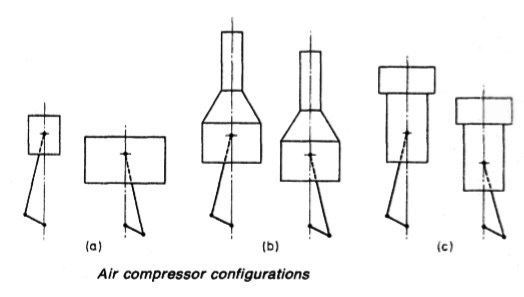
Figure 1: Multi-stage air compressor configuration
Perfect cooling for the cylinder of a single stage compressor, with constant (isothermal) temperature during the process, would remove the problems, but is impossible to achieve. Multi-stage air compressor units with various cylinder configurations and piston shapes (Figure 1 above) are used in conjunction with intermediate and after cooling to provide the nearest possible approach to the ideal of isothermal compression.
Cycle of operation
On the compression stroke (Figure 2 below) for a theoretical single cylinder compressor, the pressure rises to slightly above discharge pressure. A spring-loaded non-return discharge valve opens and the compressed air passes through at approximately constant pressure. At the end of the stroke the differential pressure across the valve, aided by the valve spring, closes the discharge valve, trapping a small amount of high pressure air in the clearance space between the piston and the cylinder head. On the suction stroke the air in the clearance space expands, its pressure dropping until such time as a spring-loaded suction valve re-seats and another compression stroke begins.
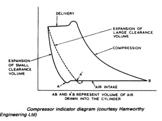
Figure 2:Compressor indicator diagram (courtesy Ham worthy Engineering Ltd)
Cooling
During compression much of the energy applied is converted into heat and any consequent rise in the air temperature will reduce the volumetric efficiency of
the cycle. To minimize the temperature rise, heat must be removed. Although some can be removed through the cylinder walls, the relatively small surface area and time available, severely limit the possible heat removal and as shown in (Figure 3) a practical solution, is to compress in more than one stage and to cool the air between the stages.
For small compressors air may be used to cool the cylinders and intercoolers, the cylinder outer surfaces being extended by fins and the intercoolers usually being of the sectional finned-tube type over which a copious flow of air is blown by a fan mounted on the end of the crankshaft. In larger compressors used for main engine starting air it is more usual to use water-cooling for both cylinders and intercoolers.
Sea water is commonly used for this purpose with coolant being circulated from a pump driven by the compressor or it can be supplied from the main sea-water circulating system. Sea water causes deposits of scale in cooling passages. Fresh water from a central cooling systems serving compressors and other auxiliaries is preferable .
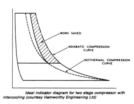
Figure 3: Ideal indicator diagram for two stage compressor with intercooling (courtesy Ham worthy Engineering Ltd)
Summarized below some of the basic procedure of machinery service systems and equipment :
- Marine air compressor
A single stage compressor used to provide air at the high pressures required for diesel engine starting, would unfortunately generate compression temperatures of a level similar to those in a diesel. Such heat would be sufficient to ignite vaporized oil in the same way as in a compression-ignition engine. The heat produced in a single stage of compression would also be wasteful of energy.....
- Air starting system
Air at a pressure of 20 to 30 bar is required for starting main and auxiliary diesel engines in motorships and for the auxiliary diesels of steamships. Control air at a lower pressure is required for ships of both categories and whether derived from high pressure compressors through reducing valves or from special control air compressors, it must be clean, dry and oil free.....
- automatic-operation-air-compressor
Before the general introduction of control equipment, air compressors were stopped and started by engine room staff, as necessary, to maintain air receiver pressure. In port or at sea, this usually meant operating one compressor for about half an hour daily unless air was being used for the whistle (during fog), for work on deck or for other purposes. ....
- Compressed air systems for steamships
A compressed air system is necessary to supply air for boiler soot-blower air motors, hose connections throughout the ship and possibly diesel generator starting. A general service air compressor would supply air at 8 bar but greater pressure (as for diesel ships) would be necessary for diesel starting.....
- Two stage starting air compressor
Hamworthy 2TM6 type which was designed for free air deliveries ranging from 183 m3 per hour at a discharge pressure of 14 bar to 367m3 per hour at 42 bar. The crankcase is a rigid casting which supports a spheroidal graphite cast iron crankshaft in three bearings.....
- Fuel handling
Fuels and lubricating oils are obtained from crude primarily by heating the crude oil, so that vapours are boiled off and then condensed at different temperatures. The constituents or fractions are collected separately in a
distillation process.....
- Fuel transfer and fire risk
The oil fuel system provides the means for delivering fuel from the receiving stations at upper deck level, port and starboard, to double-bottom or deep bunker tanks. Sampling cocks are fitted at the deck connections to obtain a representative specimen for (a) shore analysis; (b) on board testing; and (c) retention on the ship.....
- High density fuel treatment
The density of a fuel tested at 15 deg C may approach, be equal to or greater than that of water. With high density fuels, the reduction in density differential between fuel and water can cause a problem with separation but not with the usual solid impurities.....
- Viscosity controller
A continuous sample of the fuel is pumped at a constant rate through a fine capillary tube. As the flow through the tube is laminar, pressure drop across the tube is proportional to viscosity. In this unit an electric motor drives the gear pump through a reduction gear, at a speed of 40 rpm......
- Fuel blenders
Conventionally, the lower cost residual fuels are used for large slow speed diesel main engines and generators are operated on the lighter more expensive distillate fuel. The addition of a small amount of diesel oil to heavy fuel considerably reduces its viscosity and if heating is used to further bring the viscosity down then the blend can be used in generators with resultant savings.....
- Fuel heaters
The system which delivers residual fuel from the daily service tank to the diesel or boiler, must bring it to the correct viscosity by heating.For burning heavy fuel oil in a boiler furnace, or a compression-ignition engine, it is necessary to pre-heat it....
- Homogenizer
The homogenizer provides an alternative solution to the problem of water in high density fuels. It can be used to emulsify a small percentage for injection into the engine with the fuel. This is in contradiction to the normal aim of removing all water, which in the free state, can cause gassing of fuel pumps, corrosion and other problems......
- Package boiler combustion system
The elementary automatic combustion system based on a two flame burner is used for many auxiliary boilers. The burner is drawn oversize to show detail. Various different control systems are employed for the arrangement.....
- Lubricating oil treatment
Mineral oils for lubrication are, like fuel, derived from crude during refinery processes. Basic stocks are blended to make lubricants with the desired properties and correct viscosity for particular duties. ....
Home page||Cooling ||Machinery||Services ||Valves ||Pumps ||Auxiliary Power ||Propeller shaft ||Steering gears ||Ship stabilizers||Refrigeration||Air conditioning ||Deck machinery||Fire protection||Ship design
||Home ||
General Cargo Ship.com provide information on cargo ships various machinery systems -handling procedures, on board safety measures and some basic knowledge of cargo ships that might be useful for people working on board and those who working in the terminal. For any remarks please
Contact us
Copyright © 2010-2016 General Cargo Ship.com All rights reserved.
Terms and conditions of use
Read our privacy policy|| Home page||