
Home page||Machinery service system||
Fuel transfer procedure and fire risk for motorships
The oil fuel system provides the means for delivering fuel from the receiving stations at upper deck level, port and starboard, to double-bottom or deep bunker tanks. Sampling cocks are fitted at the deck connections to obtain a representative specimen for (a) shore analysis; (b) on board testing; and (c) retention on the ship. A filter on the downpipe removes large impurities.
Transfer
The fuel oil can be pumped from storage to settling tanks and also transferred if necessary, between forward and aft, port and starboard storage tanks, by means of heavy oil and diesel oil fuel transfer pumps. Transfer from settling to service tanks (Figure 1) in motorships, is via centrifuges. The latter are arranged as purifiers or clarifiers.
Fuel oil service tank An oil fuel tank that contains only the required quality of fuel ready for
immediate use. Two oil fuel service tanks, for each type of fuel used on board, necessary
for propulsion and generator systems, are to be provided. Each tank is to have a capacity
for at least eight hours operation, at sea, at maximum continuous rating of the propulsion
plant and/or generating plant associated with that tank. The arrangement for oil fuel
service tank is to be such that one tank can continue to supply oil fuel when the other is
being cleaned or opened for repair (according to Lloyds Register).
Where main engine, auxiliary engines and boilers are operated on heavy fuel oil, the
following equivalent arrangement may be accepted:
- One HFO Service Tank with a capacity of at least 8h at maximum continuous rating
(MCR) of the propulsion plant and normal operating load at sea of the generator plant
and the auxiliary boiler.
- One MDO Service Tank with a capacity at least 8h at MCR of the propulsion plant.
Where main engine and auxiliary boilers are operated on HFO and auxiliary engines are
operated on MDO, the following equivalent arrangement may be accepted:
- One HFO Service Tank with a capacity at least 8h at MCR of the propulsion plant and
normal operating load at sea of the auxiliary boiler.
- Two MDO Service Tanks, each with a capacity of at least the higher of:
- 8h at normal load at sea of the auxiliary engines,
- 4h at MCR of the propulsion plant and normal operating load at sea of the
generator plant and the auxiliary boiler.
Fire risk
Fire is an ever-present hazard with liquid fuel because the vapour from it can form a flammable/explosive mixture with air. A hydrocarbon and air mixture containing between about 1% and 10% of hydrocarbon vapour, can be readily ignited by a naked flame or spark. Combustion will also occur if the flammable mixture is in contact with a hot surface which is at or above the ignition temperature of the mixture. Ignition temperature for a hydrocarbon mixture may be about 400°C or less. A crude oil will give off flammable gases such as methane, at ambient temperature, so that the space above it is very likely to contain a flammable mixture.
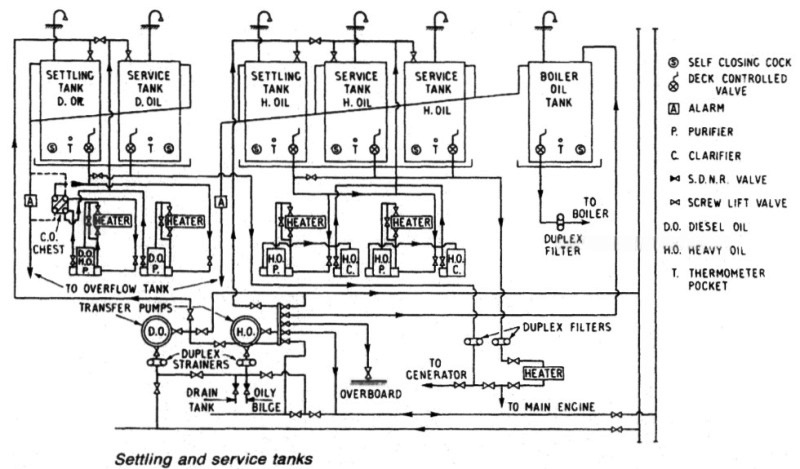
Figure 1: Settling and service tanks
Fuel oils are produced from crude in the refinery, when the gases such as methane are also extracted. Oil fuels are safer than the original crude oil. Heat will cause the evolution of hydrocarbon vapour from fuel with the quantity being related to the volatility and temperature of the fuel. The hotter the fuel, the greater the amount of vapour accumulating in the space above it. The test for the closed flash point of a fuel, is based on the heating of a fuel sample in a closed container. The heat causes evolution of vapour which accumulates in the air space above the liquid and mixes with the air. A naked flame is dipped into the container at set temperature rise intervals.
When the lower flammable limit (LFL) is reached (about 1% hydrocarbon vapour in air) ignition will occur and the mixture will burn with a brief blue flash. The temperature at which this occurs, is termed the closed flash point. There are rules governing acceptable flash points and permissible temperatures for storage and handling of oil fuel. The closed flash point of fuels for genera! use should be not less than 60 deg C, but slightly higher figures are suggested by some authorities.
Oil should not be heated to more than 51 deg C in storage and not more than 20 deg C beneath its known closed flash point. For purification and while in the service tank, then during delivery to the engine, temperatures are increased as necessary, to reduce viscosity.
Settling tanks must have thermometers and the sounding arrangements must be proof against accidental egress of oil. Drain cocks must be self-closing and the outlet valves should be capable of being closed from safe positions outside the engine or boiler room. In passenger ships, this applies also to suction and levelling valves on deep tanks. Overflow pipes and relief valves not in closed circuit should discharge to an overflow tank having an alarm device, the discharge being visible. Tank air pipes must have 25% more area than their filling pipes and should have their outlets situated clear of fire risks. They should also be fitted with detachable wire gauze diaphragms.
Provision should be made for stopping oil fuel transfer pumps from outside the machinery spaces. From the filling station pipes descend to the oil fuel main(s). These will probably be two pipes, one for heavy oil and one for diesel fuel. The system extends forward and aft in the machinery spaces, possibly extending along the shaft tunnel and, in some ships, in a duct keel or pipe tunnel. The pipes connect to the fuel transfer pump(s) and to distribution valve (or cock) chests, from which pipes run to the fuel tanks.
It was the practice to carry water ballast in empty fuel tanks and change over chests were arranged so that simultaneous connection to oil and ballast mains was not possible. Transfer pumps draw from the oil main(s), from overflow and drain tanks and from the oily bilges parts of the engine and boiler room bilges separated from the remainder by coamings to which oil spillage is led. The pumps discharge to settling tanks, the oily water separator and the oil main(s).
In
passenger ships, it must be possible to transfer oil from any tank to any other tank without use of the ballast main, but this is possible with most systems. The heavy oil and diesel oil transfer pumps can usually by cross connected if necessary. Detail and arrangements will vary with the size, type and trade of the ship. In steamships, the fuel is heated in the settling tanks by steam coils to assist water separation, and is then delivered to the burners through heaters and filters by the oil fuel pressure pumps.
In motorships, residual fuel is pumped from storage to one of, ideally, two settling tanks (Figure 1) of 24 hour capacity. Steam heating assists settling over 24 hours if possible, when any large quantities of water together with sludge, will gravitate to the bottom for removal via the drain or sludge cock. While the settling progresses in one tank, fuel from the other is being purified to the service tank which is not in use.
The purification of heavy fuel on many ships relies on one heater and a single self-sludging purifier. If problems with catalytic fines are likely or there are exceptional amounts of solid impurities, then two or even three centrifuges may be installed in series or parallel (Figure 2) arrangement. With the series arrangement, the first machine acts as a purifier, removing any remaining water and most of the solids in suspension. The second machine, set up as a clarifier, removes the finer solids remaining. The parallel arrangement shown uses two machines set up as purifiers, each having a slow throughput to permit a longer dwell time for the fuel.
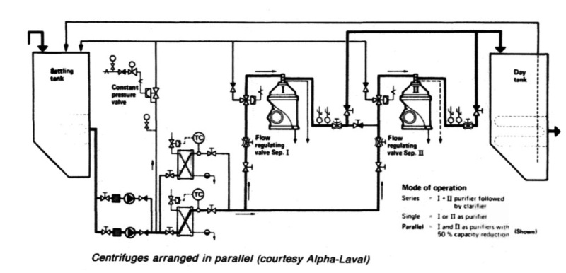
Figure 2: Centrifuges arranged in parallel
The separators can have their own pumps but the separate pumps shown, allow flow to be controlled without restricting it. Closing in a valve to throttle flow, causes turbulence which can mix fuel and impurities more closely. Clean fuel is delivered to the service tank which is not in use. Fuel from the duty service tank passes to the engine booster pump and so to the fuel pumps and injectors, through further heaters. Diesel fuel is treated similarly but more simply, with a single stage of separation and no heating.
Sludge from centrifugal separators passes to a sludge tank from which it is removed by a pump capable of handling high viscosity matter. It may be mentioned here, because it is not always understood, that fuel is heated for combustion, in order to bring it to a viscosity acceptable to the fuel injectors or burners.
Summarized below some of the basic procedure of machinery service systems and equipment :
- Marine air compressor
A single stage compressor used to provide air at the high pressures required for diesel engine starting, would unfortunately generate compression temperatures of a level similar to those in a diesel. Such heat would be sufficient to ignite vaporized oil in the same way as in a compression-ignition engine. The heat produced in a single stage of compression would also be wasteful of energy.....
- Air starting system
Air at a pressure of 20 to 30 bar is required for starting main and auxiliary diesel engines in motorships and for the auxiliary diesels of steamships. Control air at a lower pressure is required for ships of both categories and whether derived from high pressure compressors through reducing valves or from special control air compressors, it must be clean, dry and oil free.....
- automatic-operation-air-compressor
Before the general introduction of control equipment, air compressors were stopped and started by engine room staff, as necessary, to maintain air receiver pressure. In port or at sea, this usually meant operating one compressor for about half an hour daily unless air was being used for the whistle (during fog), for work on deck or for other purposes. ....
- Compressed air systems for steamships
A compressed air system is necessary to supply air for boiler soot-blower air motors, hose connections throughout the ship and possibly diesel generator starting. A general service air compressor would supply air at 8 bar but greater pressure (as for diesel ships) would be necessary for diesel starting.....
- Two stage starting air compressor
Hamworthy 2TM6 type which was designed for free air deliveries ranging from 183 m3 per hour at a discharge pressure of 14 bar to 367m3 per hour at 42 bar. The crankcase is a rigid casting which supports a spheroidal graphite cast iron crankshaft in three bearings.....
- Fuel handling
Fuels and lubricating oils are obtained from crude primarily by heating the crude oil, so that vapours are boiled off and then condensed at different temperatures. The constituents or fractions are collected separately in a
distillation process.....
- Fuel transfer and fire risk
The oil fuel system provides the means for delivering fuel from the receiving stations at upper deck level, port and starboard, to double-bottom or deep bunker tanks. Sampling cocks are fitted at the deck connections to obtain a representative specimen for (a) shore analysis; (b) on board testing; and (c) retention on the ship.....
- High density fuel treatment
The density of a fuel tested at 15 deg C may approach, be equal to or greater than that of water. With high density fuels, the reduction in density differential between fuel and water can cause a problem with separation but not with the usual solid impurities.....
- Viscosity controller
A continuous sample of the fuel is pumped at a constant rate through a fine capillary tube. As the flow through the tube is laminar, pressure drop across the tube is proportional to viscosity. In this unit an electric motor drives the gear pump through a reduction gear, at a speed of 40 rpm......
- Fuel blenders
Conventionally, the lower cost residual fuels are used for large slow speed diesel main engines and generators are operated on the lighter more expensive distillate fuel. The addition of a small amount of diesel oil to heavy fuel considerably reduces its viscosity and if heating is used to further bring the viscosity down then the blend can be used in generators with resultant savings.....
- Fuel heaters
The system which delivers residual fuel from the daily service tank to the diesel or boiler, must bring it to the correct viscosity by heating.For burning heavy fuel oil in a boiler furnace, or a compression-ignition engine, it is necessary to pre-heat it....
- Homogenizer
The homogenizer provides an alternative solution to the problem of water in high density fuels. It can be used to emulsify a small percentage for injection into the engine with the fuel. This is in contradiction to the normal aim of removing all water, which in the free state, can cause gassing of fuel pumps, corrosion and other problems......
- Package boiler combustion system
The elementary automatic combustion system based on a two flame burner is used for many auxiliary boilers. The burner is drawn oversize to show detail. Various different control systems are employed for the arrangement.....
- Lubricating oil treatment
Mineral oils for lubrication are, like fuel, derived from crude during refinery processes. Basic stocks are blended to make lubricants with the desired properties and correct viscosity for particular duties. ....
Home page||Cooling ||Machinery||Services ||Valves ||Pumps ||Auxiliary Power ||Propeller shaft ||Steering gears ||Ship stabilizers||Refrigeration||Air conditioning ||Deck machinery||Fire protection||Ship design
||Home ||
General Cargo Ship.com provide information on cargo ships various machinery systems -handling procedures, on board safety measures and some basic knowledge of cargo ships that might be useful for people working on board and those who working in the terminal. For any remarks please
Contact us
Copyright © 2010-2016 General Cargo Ship.com All rights reserved.
Terms and conditions of use
Read our privacy policy|| Home page||