
Home page||Machinery service system||
Package boiler combustion system for motor ships
The elementary automatic combustion system based on a two flame burner (Figure 1) is used for many auxiliary boilers. The burner is drawn oversize to show detail. Various different control systems are employed for the arrangement. The burner has a spring loaded piston valve which closes off the passage to the atomizing nozzle when fuel is supplied to the burner at low pressure. If the fuel pressure is increased the piston valve will be opened so that fuel passes through the atomizer. The system can supply the atomizer with fuel at three different pressures.
The solenoid valves are two-way, in that the fuel entering can be delivered through either of two outlets. The spill valves are spring loaded. When either one is in circuit, it provides the only return path for the fuel to the suction side of the fuel pressure pump. The pressure in the circuit will be forced, therefore to build up to the setting of the spill valve.
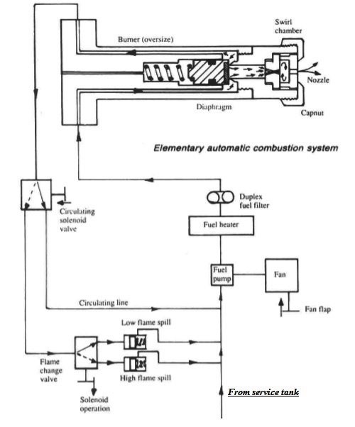
Figure 1: Elementary automatic combustion system
A gear pump with a relief arrangement to prevent excessive pressure, is used to supply fuel to the burner. Fuel pressure is varied by the operation of the system and may range up to 40 bar. Combustion air is supplied by a constant speed fan, and a damper arrangement is used to change the setting.
System operation
Control of the setup may be through various combinations of electrical, electronic or mechanical systems. An electrical control scheme is employed in this description. Electrical circuits are arranged so that when the boiler is switched on (assuming water level and other factors are correct) the system will
(1) heat up and circulate the fuel; (2) purge the combustion space of unburnt gas; and (3) ignite the flame and, by controlling it, maintain the required steam pressure. When the boiler is started, current is supplied first to the fuel heater.
The electric heating elements are thermostatically controlled and when oil in the heater reaches the required atomizing temperature, another thermostat switches in the fan and oil circulating pump. Air from the fan purges the combustion spaces for a set time, which must be sufficient to clear any unburnt gases completely. If not removed an air/gas explosive mixture may be present, so that flame ignition could result in a dangerous blowback.
The oil circulates from the pump and heater through the system via the oil circulating valve. This ensures that the oil flows through the burner until it is hot and thin enough to atomize. When the oil circulating solenoid is operated, the fuel no longer returns to the suction side of the pump but is delivered to the low flame spill through the oil change valve.
With the ignition arc 'on', oil pressure builds up sufficiently to push open the piston valve in the burner. The atomized fuel is ignited and once the flame is established, control of the oil change valve and fan damper depends on steam pressure. With low steam pressure, the oil control valve is actuated to deliver the fuel to the high flame spill. Pressure increases until this spill opens and the higher pressure forces a greater quantity of fuel through the burner. When steam pressure rises, the fuel is switched back to the low flame spill.
The fan damper is operated at the same time to adjust the air delivery to the high or low flame requirement. The solenoid or pulling motor for the operation of the high/low flame is controlled by a pressure switch acted on by boiler steam pressure. Boilers with automatic combustion systems have the usual safety valves, gauge glasses and other devices fitted for protection with additional special arrangements for unattended operation.
The flame is monitored by a photo-cell and abnormal loss of flame or ignition failure, results in shut down of the combustion system and operation of an alarm. Sometimes trouble with combustion will have the same effect if the protective glass over the photo-cell becomes smoke blackened. Water level is maintained by a float-controlled feed pump. The float chamber is external to the boiler and connected by pipes to the steam and water spaces. There is a drain at the bottom of the float chamber.
A similar float switch is fitted to activate an alarm and shut-down in the event of low water level (and high water level on some installations). Because float chambers and gauge glasses are at the water level, they can become choked by solids which tend to form a surface scum on the water. Gauge glasses must be regularly checked by blowing the steam and water cocks through the drain.
When float chambers are tested, caution is needed to avoid damage to the float. Frequent scumming and freshening will remove the solids which are precipitated in the boiler water by the chemical treatment. The boiler pressure will stay within the working range if the pressure switch is set to match output. If a fault develops or steam demand drops, then high stearn pressure will cause the burner to cut out and the fuel will circulate as for warming through.
Incorrect air quantity due to a fault with the damper would cause poor combustion. Air delivery should therefore be carefully monitored. Many package boilers bum a light fuel and heating is not required. Where a heater is in use, deviation from the correct temperature will cause the burner to be shut off. The automatic combustion system is checked periodically and when the boiler is first started up.
The flame failure photo-cell may be masked, so to test its operation or some means such as starting the boiler with the circulating solenoid cut out may be used to check flame failure shut down. Cut outs for protection against low water level, excess steam pressure, loss of air and change of fuel temperature are also checked. Test procedures vary with different boilers. At shut down the air purge should operate; the fan being set to continue running for a limited time.
Summarized below some of the basic procedure of machinery service systems and equipment :
- Marine air compressor
A single stage compressor used to provide air at the high pressures required for diesel engine starting, would unfortunately generate compression temperatures of a level similar to those in a diesel. Such heat would be sufficient to ignite vaporized oil in the same way as in a compression-ignition engine. The heat produced in a single stage of compression would also be wasteful of energy.....
- Air starting system
Air at a pressure of 20 to 30 bar is required for starting main and auxiliary diesel engines in motorships and for the auxiliary diesels of steamships. Control air at a lower pressure is required for ships of both categories and whether derived from high pressure compressors through reducing valves or from special control air compressors, it must be clean, dry and oil free.....
- automatic-operation-air-compressor
Before the general introduction of control equipment, air compressors were stopped and started by engine room staff, as necessary, to maintain air receiver pressure. In port or at sea, this usually meant operating one compressor for about half an hour daily unless air was being used for the whistle (during fog), for work on deck or for other purposes. ....
- Compressed air systems for steamships
A compressed air system is necessary to supply air for boiler soot-blower air motors, hose connections throughout the ship and possibly diesel generator starting. A general service air compressor would supply air at 8 bar but greater pressure (as for diesel ships) would be necessary for diesel starting.....
- Two stage starting air compressor
Hamworthy 2TM6 type which was designed for free air deliveries ranging from 183 m3 per hour at a discharge pressure of 14 bar to 367m3 per hour at 42 bar. The crankcase is a rigid casting which supports a spheroidal graphite cast iron crankshaft in three bearings.....
- Fuel handling
Fuels and lubricating oils are obtained from crude primarily by heating the crude oil, so that vapours are boiled off and then condensed at different temperatures. The constituents or fractions are collected separately in a
distillation process.....
- Fuel transfer and fire risk
The oil fuel system provides the means for delivering fuel from the receiving stations at upper deck level, port and starboard, to double-bottom or deep bunker tanks. Sampling cocks are fitted at the deck connections to obtain a representative specimen for (a) shore analysis; (b) on board testing; and (c) retention on the ship.....
- High density fuel treatment
The density of a fuel tested at 15 deg C may approach, be equal to or greater than that of water. With high density fuels, the reduction in density differential between fuel and water can cause a problem with separation but not with the usual solid impurities.....
- Viscosity controller
A continuous sample of the fuel is pumped at a constant rate through a fine capillary tube. As the flow through the tube is laminar, pressure drop across the tube is proportional to viscosity. In this unit an electric motor drives the gear pump through a reduction gear, at a speed of 40 rpm......
- Fuel blenders
Conventionally, the lower cost residual fuels are used for large slow speed diesel main engines and generators are operated on the lighter more expensive distillate fuel. The addition of a small amount of diesel oil to heavy fuel considerably reduces its viscosity and if heating is used to further bring the viscosity down then the blend can be used in generators with resultant savings.....
- Fuel heaters
The system which delivers residual fuel from the daily service tank to the diesel or boiler, must bring it to the correct viscosity by heating.For burning heavy fuel oil in a boiler furnace, or a compression-ignition engine, it is necessary to pre-heat it....
- Homogenizer
The homogenizer provides an alternative solution to the problem of water in high density fuels. It can be used to emulsify a small percentage for injection into the engine with the fuel. This is in contradiction to the normal aim of removing all water, which in the free state, can cause gassing of fuel pumps, corrosion and other problems......
- Package boiler combustion system
The elementary automatic combustion system based on a two flame burner is used for many auxiliary boilers. The burner is drawn oversize to show detail. Various different control systems are employed for the arrangement.....
- Lubricating oil treatment
Mineral oils for lubrication are, like fuel, derived from crude during refinery processes. Basic stocks are blended to make lubricants with the desired properties and correct viscosity for particular duties. ....
Home page||Cooling ||Machinery||Services ||Valves ||Pumps ||Auxiliary Power ||Propeller shaft ||Steering gears ||Ship stabilizers||Refrigeration||Air conditioning ||Deck machinery||Fire protection||Ship design
||Home ||
General Cargo Ship.com provide information on cargo ships various machinery systems -handling procedures, on board safety measures and some basic knowledge of cargo ships that might be useful for people working on board and those who working in the terminal. For any remarks please
Contact us
Copyright © 2010-2016 General Cargo Ship.com All rights reserved.
Terms and conditions of use
Read our privacy policy|| Home page||